Glowworm GC 41 319 08 Installation And Servicing Instructions Download Page 18

18

221051B

18

SECTION

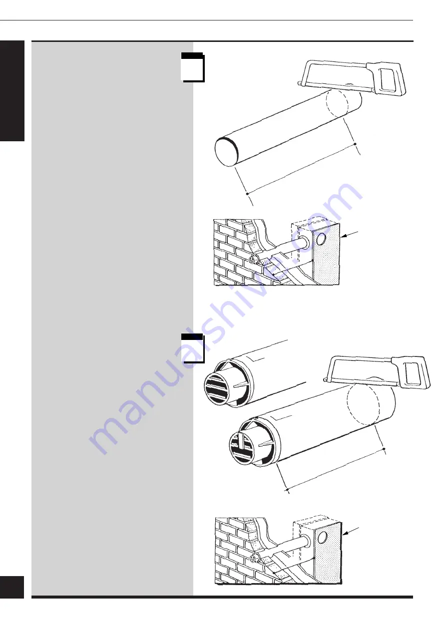
Flue Duct (Standard or
Long)

Mark the duct to length “S”+11mm then
cut square and remove any burrs.

Flue Installation

5

s t e p

9

2895

s t e p

10

Terminal/Air Duct
(Standard or Long)

Mark the duct to the length “S”+13mm
then cut square and remove any burrs.

S+11mm

S

S+13mm

WALLPLATE
/TEMPLATE

WALLPLATE
/TEMPLATE

S

1M AND 2M FLUE
TERMINAL

STANDARD
FLUE TERMINAL

Summary of Contents for GC 41 319 08

Page 1: ...To be left with user 4757 S P A C E S A V E R K F B 30 GC 41 319 08 40 GC 41 319 09 50 GC 41 319 10 This is a Cat I2H Appliance BS 6332 BS 5258 Reference in these instructions to British Standards and...

Page 2: ...material is broken Normal handling should not cause discomfort but follow normal good hygiene and wash your hands before eating drinking or going to the lavatory If you do suffer irritation to the eye...

Page 3: ...s This boiler is not suitable for outdoor locations Sheet Metal Parts WARNING When installing or servicing the boiler care should be taken when handling sheet metal parts to avoid any possibility of p...

Page 4: ...gaseous fuels Type test for purposes of Regulation 5 certified by Notified body 0086 Product production certified Notified body 0086 The CE Mark on this appliance shows compliance with 1 Directive 90...

Page 5: ...B 30 4 0 5 0 Btu h 25 476 38 217 50 630 kW 7 47 11 2 14 84 Space Saver Space Saver Space Saver Model K F B K F B K F B 30 4 0 5 0 Lifting 25 0kg 25 0kg 25 0kg Weight 55lb 55lb 55lb Total 30 0kg 30 0k...

Page 6: ...lator and must be fused 3A maximum This method of connection should be preferably an unswitched shuttered socket outlet and 3 pin plug both to the current issue of BS1363 Alternatively a double pole i...

Page 7: ...give a temperature difference of 11o C 20o F between flow and return with the thermostat set at MAX which is about 82o C 180o F High resistance microbore systems may require a higher duty pump A BYPA...

Page 8: ...ted at a maximum height of 27 5 metres 90ft above the boiler The cold feed supply must be 15mm minimum size The vent must rise continuously and be unrestricted It is important that the relative positi...

Page 9: ...fittings but positioned so that any discharge can be seen A diaphragm type expansion vessel conforming to the current issue of BS4814 see also BS7074 Part 1 and 2 must be connected at a point close t...

Page 10: ...should be made for replacing water loss from the system using a make up bottle mounted in a position higher than the top point of the system connected through a non return valve to the return side of...

Page 11: ...stallation of a boiler in a room containing a bath or shower Any electrical switch or boiler control using mains electricity should be so situated that it cannot be touched by a person using the bath...

Page 12: ...IDE 168cm2 26in2 168cm2 26in2 84cm2 13in2 84cm2 13in2 Cupboard or Compartment Ventilation Where the boiler is fitted in a cupboard or compartment permanent high and low level ventilation must be provi...

Page 13: ...le spacings from the terminal to obstructions and ventilation openings are as shown in the diagram Where the terminal is fitted within 600mm 24in below plastic guttering an aluminium shield 1500mm 5ft...

Page 14: ...POSITION BEFORE PROCEEDING Refer to the relevant diagrams in Section 4 For wall thickness of less than 300mm the boiler can be fully installed from inside For a wall thickness of over 300mm the cut ho...

Page 15: ...the wall sleeve Make good around the wall sleeve at both internal and external wall faces through the wall sleeve if internal access is only available If the wall thickness Q is greater than 300mm the...

Page 16: ...TERMINAL Q Q 11mm 2893 s t e p s t e p 4 5 s t e p 1 1 Continue at Flue Duct Mark the duct to the length Q 11mm then cut square and remove any burrs Air Duct Terminal Mark the duct to the length Q 13...

Page 17: ...unting hole positions Remove the wallplate template drill the holes and then secure the wallplate template with the fittings provided WALL SLEEVE If the wall thickness Q is less than 300mm cut the wal...

Page 18: ...t square and remove any burrs Flue Installation 5 s t e p 9 2895 s t e p 1 0 Terminal Air Duct Standard or Long Mark the duct to the length S 13mm then cut square and remove any burrs S 11mm S S 13mm...

Page 19: ...erminal and flue duct assembly as shown making sure of the correct alignment of the TOP s Drill two 3mm diameter holes through the air duct terminal and flue manifold Secure the air duct terminal to t...

Page 20: ...cover the hole in the wall On all installations push the flue assembly into and through the wall sleeve and hole such that it is within the wall sleeve and does not stick out into the room Do not pus...

Page 21: ...N FITTING A SIDE FLUE FOLLOW STEPS Remove the inner case by releasing the screws at the bottom and unhooking at the top place on one side until required Remove the violet and red electrical connection...

Page 22: ...bove the top mounting bracket allow the boiler to slide down the wall onto the top and bottom wall mounting brackets Check the engagement by pulling the boiler forwards at its base there should be no...

Page 23: ...n outlet extension over the flue manifold spigot If removed refit the control box combustion chamber by reversing the instructions in Section 6 step 18 and Section 10 steps 3 5 6 7 8 and 9 Reconnect t...

Page 24: ...SLOT REAR VIEW BLANKING PLATE GASKET FAN REAR OUTLET EXTENTION FAN SECURING SCREW FLUE HOOD ASSEMBLY SECURING SCREW GASKET RIGHT HAND FLUE HOOD ASSEMBLY FAN SIDE OUTLET EXTENTION LEFT HAND FLUE HOOD A...

Page 25: ...g weight remove the electrical control box and combustion chamber assembly by following the instructions in Section 6 step 18 and Section 10 steps 3 5 6 7 8 and 9 Lift the boiler into position above t...

Page 26: ...n outlet extension onto the flue manifold spigot When correctly located secure the assembly by fitting the other extended brass screw and tighten both down Secure the flue assembly to the boiler using...

Page 27: ...ight Gas Supply Connection Remove the electrical controls box cover Connect the gas supply to the gas service cock on the boiler making sure it is turned off Check for gas soundness up to the cock in...

Page 28: ...must be earthed The incoming cables should be routed from the right hand side of the boiler Remove the terminal connection plug as shown The electrical installation must comply with the current issue...

Page 29: ...e system until the pressure gauge registers 1 5bar 21 5lbf in2 Clear any airlocks and check for water soundness Check the operation of the safety valve by allowing the water pressure to rise until the...

Page 30: ...ilot gas rate is preset and MUST NOT be adjusted see Servicing Step 15 For future reference attach the self adhesive arrow indicator from the loose items pack to the data badge against the rating that...

Page 31: ...boiler and test the polarity of the mains supply Turn the boiler thermostat knob fully clockwise to the maximum setting The lighting sequence is automatic as follows The fan operates The spark ignitio...

Page 32: ...urning appliances and pilot lights are off Space Saver K F B 30 Approx Gas Rate min med max m3 h 0 7 0 9 1 0 ft3 h25 31 37 Space Saver K F B 40 Approx Gas Rate min med max m3 h 1 1 1 2 1 4 ft3 h38 43...

Page 33: ...sting the pump and lockshield valve as necessary Having achieved a satisfactory condition operate the boiler with the bypass closed on minimum load normally central heating only with one radiator oper...

Page 34: ...panel assembly has been designed with a variable adjustment to suit a range of available kitchen furniture 700mm 728mm high by 285mm 315mm deep and will also suit most installations in a cupboard It i...

Page 35: ...rvals The frequency of servicing will depend upon the particular installation conditions and usage but in general once a year should be enough It is the law that servicing is carried out by a competen...

Page 36: ...completing any servicing always test for gas soundness and if necessary carry out functional checks of controls Access Remove the electrical control box cover by removing the four screws Note As an a...

Page 37: ...to kink the capillaries When replacing the phials make sure that they are still covered with heat sink compound s t e p 7 2910 FAN FLUE HOOD SCREW 2 PHIAL POCKET SPLIT PIN OVERHEAT CUT OFF PHIAL THER...

Page 38: ...ly by removing the ten securing screws withdraw the complete assembly Slacken the air pressure pipe union and turn through 90o Remove the rear flueway cleaning plate Remove the heat exchanger front co...

Page 39: ...cover Tighten down the fan flue screws Refit the cleaning plate Main Burner Remove the main burner by releasing the two securing screws and nuts as shown Brush or vacuum away any deposits make sure th...

Page 40: ...ce as shown Remove the pilot burner securing screws to release the pilot burner and electrode assembly Clean the pilot burner and electrode Remove the pilot injector by unscrewing it from the pilot bu...

Page 41: ...resetting Remove the front panel as Section 1 Step 1 and press the reset button on the top of the electrical controls box cover see diagram at Step 3 If the cutoff operates at any other time press th...

Page 42: ...H CONTROL THERMOSTAT Remove RED link between 7 and 12 when fitting a time control etc If no switch is fitted the pump will run continuously E N L N L E 12 11 10 9 8 7 6 5 NC NO C 1 2 3 9 8 6 7 3 KEY b...

Page 43: ...th mains supply or PCB fuse Overheat cut off device tripped or thermostat overheat cut off device faulty see detailed fault finding chart Air flow proving fault that is fan or air pressure switch see...

Page 44: ...trical supply polarity and correct if necessary If satisfactory replace printed circuit board Isolate supply test harness continuity If satisfactory replace printed circuit board Correct power supply...

Page 45: ...p running to allow the boiler to cool down after which it will stop providing the remote controls are NOT calling for heat Turn off remote controls does the pump stop after a short period of time Faul...

Page 46: ...rictor is in place Remove the pilot burner by unscrewing the two securing screws as shown The pilot burner or injector can now be replaced Electrode Gain access as Section 10 steps 1 to 4 Pull off the...

Page 47: ...Control Thermostat and Overheat Cutoff Gain access as Section 10 steps 1 to 5 Control Thermostat Pull off the control thermostat knob remove the two screws securing the thermostat to the control box...

Page 48: ...sconnect the gas service cock union Transfer the half union of the gas service cock to the inlet of the replacement gas valve Also transfer the pilot supply pipe make sure that the restrictor is in pl...

Page 49: ...2 EARTH CONNECTION Fan Gain access as Section 10 steps 1 2 and 5 Remove the electrical connections and disconnect the air tubes Remove the fluehood fan assembly securing screws and withdraw the assem...

Page 50: ...he insulation and fit the replacement parts ensuring they are fitted as shown Viewing Window Gain access as Section 10 steps 1 to 4 Remove the two screws and then the window When replacing take care n...

Page 51: ...dering When ordering any spare parts please quote the part number and description from the list together with the model name and serial number If ordering from British Gas also quote the GC number of...

Page 52: ...tch Yamatake 40 50 313 303 6A 230000 Air pressure switch Yamatake 30 385 860 7 203428 Pilot assembly inc 8 and 14 313 304 8 203509 Pilot injector 394 163 9 203099 Main injector 30 313 389 9 205700 Mai...

Reviews: