


Supplied By www.heating spares.co Tel. 0161 620 6677
17
221764B
8 Servicing
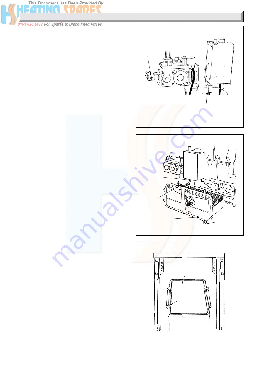
ACCESS TO FLUEWAY
Diagram 8.3
0908
FLUEWAY
CLEANING
DOOR
SELF-
TAPPING
SCREW (4)
ACCESS FOR SERVICING
Diagram 8.2
9018
GRAPHITE
COATED NUT
TIE
BAR
SECURING
SCREW (5)
BAFFLE
TRAY
PIPE
SUPPORT
BRACKET
COMBUSTION
CHAMBER
COVER
It is the law that servicing must be carried out by a competent
person.
Before commencing any servicing, turn off the gas supply at the
gas service cock, see diagram 8.1 and isolate the electrical
supply to the boiler.
Always test for gas soundness after completing any servicing or
replacement of parts.
8.1 Gain Access to the Boiler
Pull the door forward at the top to disengage studs and lift to
release from the slots, see diagram 7.3.
Lift the plinth front up and forwards to withdraw, see diagram
7.3.
If the top casing is removed during servicing care must be taken
not to damage or lose any plastic pegs when replacing it. Refer
to Section 5.3 “Top Casing” when refitting.
8.2 Boiler Flueways
Unscrew the union nut securing the gas service cock to the gas
valve, see diagram 8.1.
Remove the mains inlet connector by pulling downwards, see
diagram 8.1
Remove split pin on the thermostat phial pocket and withdraw
the phial and capillary, see diagram 4.5.
Remove the five screws retaining the combustion chamber
cover and burner assembly, see diagram 8.2.
Ease the gas service cock away from the gas valve and unhook
the pipe support bracket from the tie bar to enable the assembly
of cover, control box, gas valve and burners to be withdrawn
forwards.
Remove graphite coated nut to release baffle tray and remove
from combustion chamber, taking care not or damage the
insulation material in the sides of the chamber.
Remove the self-tapping screws which retain the flueway cleaning
door and lift door clear, see diagram 8.3.
Remove the baffles from the heat exchanger, see diagram 8.6.
Place a sheet of paper in the combustion chamber to catch any
flue debris.
Access for flueway cleaning is made through the cleaning door
and combustion chamber apertures.
Thoroughly clean boiler flueways and fins from top and bottom
with a suitable stiff brush. Remove any debris from the base of
the combustion chamber.
Check that the flueways are clear, view with the aid of a mirror
or reflector.
8.3 Burners and Injectors
Refer to Section 8.2 for instructions on how to remove cover,
burners and controls assembly.
Remove the two screws and nuts securing each burner support
bracket to the combustion chamber cover, see diagram 8.4.
Remove the graphite coated nuts on supply feed pipe at the rear
of the burner to release the burners, taking care not to damage
the pilot burner and shield when removing.
Remove the nuts, washers and burner end caps, see diagram
8.5.
Remove the distributors from inside the burners then clean the
burners and components thoroughly with a vacuum cleaner.
Check that the main burner injectors are not blocked or damaged.
Clean or renew as necessary. Do not clean with a wire or sharp
instrument, see diagram 8.4.
8.4 Service Checks
Inspect the thermocouple and pilot burner, clean or renew as
necessary.
Diagram 8.1
ISOLATION OF
GAS AND ELECTRICITY
9012
GAS
SERVICE
COCK
(turn off)
(shown
closed)
MAINS INLET
CONNECTOR
(pull downwards)