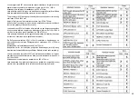
background image

SOMMARIO

INDEX

SOMMAIRE

INHALT

INDICE

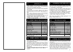
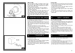
1 - GENERAL INFORMATION
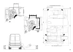
2 - TECHNICAL DATA 
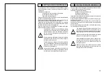
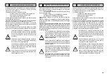
3 - GENERAL SAFETY REGULATION
4 - SAFETY DEVICES 
5 - TRANSPORT 
6 - UNPACKING
7 - INSTALLATION 

7.1 Installation place   

7.2 Workplace requirements

7.3 Installation and assembly


7.4 Electrical connection

7.5 Preliminary operations

7.6 Folding the machine down

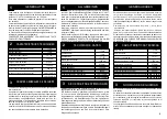
8 - LAYOUT OF FUNCTIONAL PARTS
9  -  IDENTIFYING  WARNING  SIG-

NALS 

10 - IDENTIFICATION OF CONTROL
11- WORKING POSITION
12  -  CORRECT  OPERATION 

CHECKS 
13 - OPERATION

13.1 Locking the wheel

         Light-alloy rim locking

13.2 Tubeless and supersingle wheels

         Bead breaking

         Demounting 


13.3 Assembly with tubular tool


14 - ORDINARY MAINTENANCE
15 - TROUBLE SHOOTING 
16- MOVING THE MACHINE
17- STORING 
18- SCRAPPING A MACHINE 
19- DATA ON SERIAL PLATE
20- ACCESSORIES

1 - GENERALITA' 
2 - CARATTERISTICHE TECNICHE 
3 - NORME DI SICUREZZA
4 - DISPOSITIVI DI SICUREZZA
5 - TRASPORTO 
6 - DISIMBALLO
7 - INSTALLAZIONE

7.1 Luogo di installazione 

7.2 Posizionamento 

7.3 Installazione e montaggio

7.4 Allacciamento elettrico

7.5 Operazioni preliminari

7.6 Chiusura macchina

8-  RAPPRES.  DELLE  PARTI  FUN-

ZIONALI

9  -  IDENTIFIC.  SEGNALI  DI  PERI-

COLO

10 - IDENDIFICAZIONE DEI COMANDI
11 - POSIZIONE DI LAVORO
12 - CONTROLLO CORRETTO FUN-

ZION.
13 - USO

13.1 Bloccaggio ruota 

         Bloccaggio cerchi in lega 

13.2 Ruote tubeless e supersingle

         Stallonatura

         Smontaggio 


13.3 Montaggio con utensile a rullo


14 - MANUTENZIONE ORDINARIA
15 - INCONVENIENTI/CAUSE/RIMEDI
16-MOVIMENTAZIONE 
17-ACCANTONAMENTO 
18-ROTTAMAZIONE 
19-DATI DI TARGA 
20- ACCESSORI 

1 - GENERALITES
2 - CARACTERIST. TECHNIQUES
3 - NORMES DE SECURITE
4 - DISPOSITIFS DE SECURITE
5 - TRANSPORT
6 - DEBALLAGE
7 - INSTALLATION

7.1 Lieu d’installation

7.2 Mise en place

7.3 Installation et montage

7.4 Branchement électrique

7.5 Opérations préalables

7.6 Fermeture machine

8 - REPRES. DES PIECES FONCION-

NELLES

9  -  IDENTIFIC.  DES  SIGNAUX  DE 

DANGER

10 - IDENTIFICATION DES COMMAN-

DES

11 - POSITION DE TRAVAIL
12 - CONTROLE DU BON FONCTIONN.

13 - UTILISATION

13.1 Blocage de la roue

         Blocage des jantes en alliage

13.2 Roues tubeless et supersingle

         Détalonnage

         Démontage


13.3 Montage de l’outil à rouleau


14 - ENTRETIEN ORDINAIRE
15 - INCONV./CAUSES/REMEDES
16 - MANUTENTION
17 - REMISAGE
18 - MISE A DECHARGE
19 - PLAQUE SIGNALETIQUE

20 - ACCESSOIRES

1 - ALLGEMEINES
2 - TECHNISCHE DATEN
3 - SICHERHEITSBESTIMMUNGEN
4 - SICHERHEITSVORRICHTUNGEN
5 - TRANSPORT
6 - AUSPACKEN
7 - INSTALLATION

7.1 Standort

7.2 Aufstellung

7.3 Installation und Montage

7.4 Stromanschluss

7.5 Vorbereitende Eingriffe

7.6 Schließen der Maschine

8 - DARSTELLUNG DER WICHTIGSTEN  

      MASCHINENTEILE

9 - KENNZEICHNUNG DER WARNSIG-

NALE

10- KENNZEICHNUNG DER BEDIENUNG-

SEL.

11 - ARBEITSPOSITION
12  -  PRÜFUNG AUF  KORREKTEN 

BETRIEB
13 - BENUTZUNG

13.1 Radaufspannen

         Aufspannen von Alu-Felgen

13.2 Schlauchlose und Supersingle-Räder

         Abdrücken

         Demontage


13.3 Montage mit Rollenwerkzeug


14 - WARTUNG
15 - FEHLERSUCHE
16 - BEWEGEN 
17 - LAGERHALTUNG
18 - VERSCHROTTEN
19 - DATEN DES TYPENSCHILDS
20 - ZUBEHÖR

1 - GENERALIDADES
2 - CARACTERÍSTICAS TÉCNICAS 
3 - NORMAS DE SEGURIDAD
4 - DISPOSITIVOS DE SEGURIDAD
5 - TRANSPORTE 
6 - DESEMBALAJE
7 - INSTALACIÓN

7.1 Lugar de instalación

7.2 Colocación de la máquina

7.3 Instalación y montaje

7.4 Conexión eléctrica

7.5 Operaciones preliminares

7.6 Cierre de la máquina

8- REPRES. PARTES FUNCIONALES 
9- IDENTIF. SEÑALES DE PELIGRO
10- IDENTIFICACIÓN COMANDOS
11- POSICIÓN DE TRABAJO
12-CONTROL CORRECTO FUNCION

13 - UTILIZACIÓN

13.1 Bloqueo de la rueda

         Bloqueo llantas de aleación

13.2 Ruedas tubeless y supersingle

         Destalonamiento

         Desmontaje 


13.3 Montaje con útil de rodillo


14 - MANTENIMIENTO ORDINARIO
15  -


PROBLEMAS  /  CAUSAS  /  SOLU-

CIONES

16 - TRASLADO 
17 - ALMACENAMIENTO 
18 - DESGUACE 
19 - DATOS DE MATRÍCULA 
20 - ACCESORIOS

4/5
4/5
4/5
8/9
8/9

10/11
10/11

10/11

10/11

13/14

1516

17/18

19/20
21/22
23/24
25/26
25/26
25/26

29/30

29/30
33/34

33/34

33/34
36/37
37/38
39/40
41/42
41/42
41/42
43/44
43/44

Summary of Contents for S 561

Page 1: ...nales INSTALLATION BEDIENUNG UND WAR TUNG Originalbetriebsanleitung MANUAL DE INSTRUCCIONES Manual de instrucciones original SMONTAGOMME UNIVERSALE PER SERVIZIO MOBILE UNIVERSAL TRUCK TYRE CHANGER FOR...

Page 2: ...REINSTIMMUNG DECLARACION CE DE CONFORMIDAD al quale questa dichiarazione si riferisce E CONFORME ALLE SEGUENTI DIRETTIVE to which declaration refers is in conformity with the FOLLOWING DIRECTIVES au q...

Page 3: ...et und 2003 108 CE RAEE e le disposizioni di Legge del Paese di destinazione della macchina apparecchiatura as well as with the national laws in force in the Country of Installation ainsi qu aux lois...

Page 4: ...ucteur ou les revendeurs autoris s This equipment is subject to the regulations foreseen by Directives 2002 96 CE and 2003 108 CE RAEE and therefore it cannot be scrapped as a generic scrap material b...

Page 5: ...TIFIC DES SIGNAUX DE DANGER 10 IDENTIFICATION DES COMMAN DES 11 POSITION DE TRAVAIL 12 CONTROLE DU BON FONCTIONN 13 UTILISATION 13 1 Blocage de la roue Blocage des jantes en alliage 13 2 Roues tubeles...

Page 6: ...achine for straightening rims breaking beads of still inflated or dirty tyres turning rasping cutting tyres The Manufacturer shall not liable for any injury to persons or damage to things caused by im...

Page 7: ...on Personal benutzt werden das speziell angeleitet wurde und dazu eine Genehmigung hat Ein Bediener wird als qualifiziert bezeichnet wenn er die im vom Hersteller bereitgestellten Bedienungs und War t...

Page 8: ...ive headphones they shall NOT wear any form of clothing that could get caught up or restrict the operator s movements The operator must be able to read and understand the danger warnings understand th...

Page 9: ...as de besoin Le d monte pneu ne doit en aucun cas tre utilis par des personnes souffrant d un quelconque handicap dans le cas o cela compromettrait la s curit durant l utilisation Toute intervention n...

Page 10: ...na viene fornita fissata sul pallet con gabbia in legno Lo smontagomme deve essere trasportato nell imballo originale e mantenuto nella posizione indicata sull imballo stesso Lo spostamento della macc...

Page 11: ...u dans la position indiqu e sur ce dernier le d placement de la machine dans on emballage doit s effectuer avec un chariot l vateur de port e appropri e en pla ant les fourches hauteur dans les points...

Page 12: ...nstallation is outdoor it must be protected by some kind of roofing against rain The following work environment conditions are applicable Relative humidity from 30 95 without condensation Temperature...

Page 13: ...la m quina permanezca estable y permita a los rodillos de la pedana correr libremente Si la m quina se instala en un lugar abierto es necesario protegerla de la lluvia con una marquesina Las condicion...

Page 14: ...dimensions minimum de 1100 x 1600 H mm Hauteur au sol du plan d installation de 500 700 mm Liste indicative de mod les de fourgonnettes permettant l installation il incombe au client de s assurer de l...

Page 15: ...e rendendo l utilizzo pericoloso In base al tipo di furgone in possesso occorre determina re adeguati sistemi di fissaggio in maniera da bloccare in modo sicuro lo smontagomme al furgone stesso The ty...

Page 16: ...B 1 sa position doit tre telle que la ridelle lat rale puisse tre ferm e correctement sans heurter le d monte pneu Fixer le d monte pneu hauteur de 4 points minimum au plateau du v hicule en effectuan...

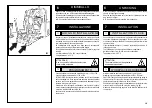
Page 17: ...15 B 1 Min 1100 mm Min 1600 mm...

Page 18: ...re della centralina oleodinamica sia quello indicato dalla freccia 6 fig B 3 In caso contrario fare invertire tra loro da personale specia lizzato due fili nella spina del cavo di alimentazione CONTRO...

Page 19: ...er sich aus der Nichtbeachtung dieserAnweisungen ergibt enthebt den Hersteller von jeder Haftung und f hrt zum Verfall des Garantieanspruchs Arbeiten an der elektrischen Anlage auch kleineren Umfangs...

Page 20: ...e apporre al di fuori del furgone un lampeg giante di pericolo arancione D E Durante l utilizzo dello smontagomme con gruppo elet trogeno avviato e compressore in funzione CONSI GLIABILE indossare una...

Page 21: ...acer la cl en position 1 de chauffage et une fois le t moin jaune allum placer la cl sur la position 2 pour la mise en marche L op ration de mise en marche du groupe g n rateur compresseur doit tre co...

Page 22: ...ispetto al motore fig B9 Seguire correttamente le fasi descritte sopra per evitare manovre pericolose o danni alle parti dello smonta gomme C D F B 6 B 7 B 8 B 9 PUTTING THE MACHINE AWAY Once you have...

Page 23: ...sitif auto centrant faire pivoter le dispositif auto centrant et placer une griffe en position perpendiculaire au moteur lectrique du mandrin fig B 8 l aide du levier 8 fig C page 20 placer le bras po...

Page 24: ...sere raccolti 1 Gruppo elettrogeno 2 Braccio porta autocentrante 3 Autocentrante 4 Piede di appoggio 5 Consolle di comando 6 Utensile a rullo 7 Comando movimento destra sinistra carrello 8 Comando sal...

Page 25: ...le from moving parts of the machine Neck laces bracelets and too large clothes can be dangerous for the operator 1 Stromerzeugungsaggregat 2 Spannfuttertragearm 3 Spannfutter 4 St tzfu 5 Bedienkonsole...

Page 26: ...cante di una o pi targhette di pericolo Non interporre oggetti che ne ostrui scano la visione all operatore Per eventuali richieste utilizzare il codice indicato nella presente tavola 3005419 3005423...

Page 27: ...add any object that could prevent the operator from seeing the labels Use the code in this table to order labels you need ATTENTION Si les plaques signal ti ques de danger sont peu lisibles ou si elle...

Page 28: ...column fig C enables the operator to work in any position around the machine whichever is most convenient on a case to case basis On this mobile control column the following controls are located The...

Page 29: ...diqu par les fl ches plac es sur la p dale Sur le d monte pneu sont galement mont s La poign e 15 Fig D qui permet de basculer le bras porte outil 14 Fig D de la position de travail la position hors s...

Page 30: ...entrante 3 Fig C1 deve ruotare in senso orario premere il pedale a bilanciere sul lato sinistro l autocentrante deve ruotare in senso antiorario 3 Depress the right pedal 10 Fig C the spindle 3 Fig C1...

Page 31: ...c t gauche le mandrin doit tourner dans le sens inverse Por tanto antes de todo accionar la manilla 15 Fig D para colocar el brazo en esta posici n ATENCI N El descenso del brazo porta tiles crea punt...

Page 32: ...g C1 in posizione chiusa avvicinare la ruota all autocentrante agire sulla leva 9 fig C per aprire l autocentrante e bloccare cos il cerchio internamente e nella posizione pi conve niente che va scelt...

Page 33: ...r au sol et les sou lever l aide d un moyen de levage m canique appropri 3 Relever ou abaisser le bras de fa on centrer au mieux le mandrin auto centrant 3 fig C1 par rapport la jante 4 Avec les griff...

Page 34: ...cerchi in lega 138 90 BLOCCAGGIO CERCHI IN LEGA ATTENZIONE Non abbandonare il posto di lavoro con la ruota bloccata sull autocentrante e sollevata da terra LIGHT ALLOY RIM LOCKING The 137 90 clamps es...

Page 35: ...ndommager Les griffes 137 90 se fixent ba onnette sur le support de la griffe du mandrin voir figure E 7 Gr ce une vis oreilles les griffes peuvent tre bloqu es sur le support Bloquer la jante de la m...

Page 36: ...le evitare di com piere l operazione 6 per passare da un tallone all altro Agganciando il braccio portautensile nella posizione di lavoro cen trale X possibile dopo aver sollevato il pneumatico trasla...

Page 37: ...pen verlegen und in zweiter Arbeitsstellung wieder festmachen Die H nde nicht auf dem Werkzeug halten wenn es inArbe itsstellung wiedergestellt wird um m gliche Quetschungen zwischen Werkzeug und Rad...

Page 38: ...mantenere in equilibrio la ruota Le ruote non devono mai essere sollevate dall operatore si deve farle rotolare sul pavimento per ruote pesanti oltre 110 kg e o di grandi dimensioni diametro oltre 130...

Page 39: ...efindet Erster Wulst soll in Stellung getreten sein Abb 25 8 Rollenwerkzeug 4 5 mm fern von Felge stellen und auf den zweiten Reifenwulst dr cken um die Zange einzuf gen Abb 25 9 Rechts drehen indem s...

Page 40: ...sia il carter riduttore che il serbatoio centralina sono dotati di appositi tappi di scarico To ensure that this tyre changer works perfectly over the years carry out the routine maintenance schedule...

Page 41: ...nachf llen ISO L HV VG46 Persian Oil Idrol T oder gleichwertige Sorten Bsp Esso Invarol EP Agip Arnica Mobil DTE 15 Fina Hydran HV Shell Tellus T Total Equivis ZS Castrol Hyspin AWH HV BP Bactram HV C...

Page 42: ...the mains electric supply REMEDIES PROBLEMA PROBLEM After having switched the general button on the general warning light also switches on but the motor on the hy draulic power pack does not function...

Page 43: ...aufen zu bringen oder wenn St rungen irgendwelcher Art vorliegen verwenden Sie die Maschine NICHT sondern verst ndigen umgehend den technischen Kundendienst ST RUNGEN 1 Den Stecker richtig in die Netz...

Page 44: ...con un cappuccio in nylon Nel caso di rimessa in uso dopo un periodo di accantonamento sar necessario Inserire nuovamente i liquidi di funzionamento nei serbatoi If the machine has to be stored for a...

Page 45: ...eb erforderliche Fl ssigkeiten enthalten und die ganze Maschine vor Staub sch tzen indem man sie mit einer Nylonhaube abdeckt Wenn die Maschine sp ter wieder in Betrieb genommen werden soll ist folgen...

Page 46: ...ne della macchina riportante 1 Dati del costruttore 2 Modello 3 Numero di serie 4 Fase 5 Voltaggio 6 Frequenza 7 Assorbimento 8 Anno di costruzione 9 Peso della macchina 10 Potenza assorbita The manuf...

Page 47: ...el Vereinfacht die Montage der W lste bei Schlauchreifen 20 ZUBEHOER 19 Auf der R ckseite der Maschine befindet sich das Typenschild der Maschine auf dem folgende Angaben stehen 1 Herstellerdaten 2 Mo...

Page 48: ...03 04 PRESA VOLANTE 3Ph N T GW62009 cod MCC0459 PE MOTORE POMPA 3PH 230 400V 50 60HZ 2HP B5 cod 4596777 L 2 5 m L 7 m L 3 m L 2 m 7 71 2x1mmq L 2 m Cod 4596726 NO Cod 4595082 NC Cod 4595082 NC 5x1mmq...

Page 49: ...LICO FILTRO MOT 3PH 230 400V 50 60HZ 1 5 1 8 KW cod 4596777 POMPA GR 1 4 8 cc giro cod 4195706 SERBATOIO OLIO CILINDRO APERTURA CHIUSURA AUTOCENTRANTE CILINDRO RIBALTAMENTO MACCHINA CILINDRO SALITA DI...

Page 50: ...GIULIANO INDUSTRIAL S p A Via Guerrieri 6 42015 CORREGGIO ITALY Tel 39 522 73 11 11 Fax 39 522 63 31 09 E mail info giuliano automotive com http www giuliano automotive com...

Reviews:

Related manuals for S 561