16
7.4
7.4
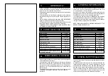
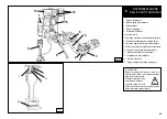
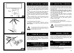
ELECTRIC HOOK UP
B/2
ALLACCIAMENTO ELETTRICO
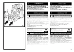
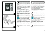
Esiste la possibilità di collegare la macchina ad una presa di tensione
evitando così l'utilizzo del gruppo elettrogeno.
Verificare le caratteristiche della presa di corrente e del cavo di con-
nessione. Collegare la spina alla presa
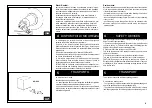
A
, ruotare l'interruttore genera-
le
B
; in questo modo avremo l'accensione del gruppo motore pompa
e del compressore ed il completo funzionamento della macchina.
Utilizzare lo stesso collegamento anche per il modello di macchina-
privo di gruppo elettrogeno.
Interventi sull'impianto elettrico, anche di
lieve entità, richiedono l'opera di
personale professionalmente qualificato.
Ogni danno derivante dalla mancata osservanza delle suddette indica-
zioni non sarà addebitabile al costruttore e comporterà la decadenza
delle condizioni di garanzia.
380 V. - 3 Ph. - 50/60 Hz.
Corrente nominale
16 A AM
Alimentazione
Interrutt.
Fusibile
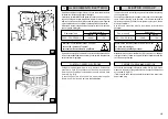
Collegare lo smontagomme alla rete, azionare l'interruttore
generale (A, fig. B/2) e verificare che il senso di rotazione del
motore della centralina oleodinamica sia quello indicato dalla
freccia (6, fig. B/3).
In caso contrario fare invertire tra loro, da personale specia-
lizzato, due fili nella spina del cavo di alimentazione.
CONTROLLO SENSO DI ROTAZIONE
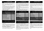
The machine can be connected to a power socket without thus having
to use a generator.
Check the specifications of the power socket and of the connection
cable. Connect the plug to the socket
A
, turn the main switch
B
to
switch the pump motor unit and the compressor on, thus the machine
will work completely.
Use the same connection also for the machine version without
generator.
Work on the electric system, even if minor, must
be done exclusively by
professionally qualified personnel.
Manufacturer shall not be liable for any injury to persons or damage
to things caused by failure to comply with these regulations and can
cancel warranty coverage.
380 V. - 3 Ph. - 50/60 Hz.
Rated current
16 A AM
Power supply
Fuse
Connect the tyre changer to the mains, switch “ON” (A, fig. B/2) and
make sure the motor of the gearbox runs in the direction pointed out
by the arrow (6, fig. B/3).
If this is not the case, have a specialist invert two of the wires in the
power cable plug.
CHECKING THE RUNNING DIRECTION
Switch
16 A
16 A
B/3
6
Summary of Contents for S 561
Page 17: ...15 B 1 Min 1100 mm Min 1600 mm...

