background image

36

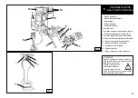
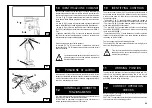
13.3_Montaggio con utensile a rullo.

1)

 Assicurarsi che il cerchio sia bloccato sulla flangia.

2)

 Lubrificare i talloni del pneumatico e il cerchio con il grasso in  

  dotazione. 

3)

 Serrare la pinza al bordo esterno del cerchio, nel punto più alto.

4)

 Posizionare il pneumatico sulla pedana ed abbassare la flangia  

  per agganciare il primo tallone alla pinza (avendo cura di 

  mantenere quest'ultima nel punto più alto).

5)

 Sollevare il cerchio con il pneumatico agganciato e ruotarlo in  

senso antiorario di 15-20 cm. Il pneumatico si posizionerà in modo    

obliquo rispetto al cerchio.

6)

 Abbassare il braccio porta utensili (6, pag 20) in posizione di lavoro,  

fino a che si sarà agganciato con l'apposito cricchetto. 

Verificare sempre che il braccio sia correttamente 

agganciato al carrello. 
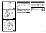
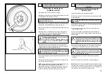
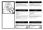
7)

 Agendo sulle leve (7) (8) posizionare il rullo contro il secondo 

tallone del pneumatico e ruotare il pneumatico fino a portare la pinza 

nel punto piu basso. Il primo tallone dovrebbe essere entra- to. (Fig. 

25)

8)

 Posizionare il rullo a 4-5 mm. di distanza dal cerchio e premere  

  sul secondo tallone del pneumatico per inserire la pinza. (Fig. 25)

9)

 Ruotare in senso orario lubrificando con apposito grasso e contem-

poraneamente fare avanzare il rullo a brevi scatti verso il centro  

del cerchio fino al completo inserimento del pneumatico sul       

cerchio. (Fig. 26).

10)

 Togliere la pinza dal cerchione e portare il rullo in posizione di  

fuori lavoro.

11)

 Posizionare la pedana sotto la verticale della ruota e abbassare 

il braccio porta flangia per adagiarvi sopra la ruota.

12)

 Svitare la manovella di bloccaggio avendo cura di sostenere la  

  ruota per evitarne la caduta, traslare la pedana e rimuovere la  

  ruota stessa.

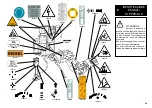
Questa operazione può essere estremamente pericolosa! 

Effettuarla manualmente solo nel caso si sia assolutamente 

sicuri di riuscire a mantenere in equilibrio la ruota. Le ruote 

non devono mai essere sollevate dall'operatore, si deve farle 

rotolare sul pavimento per ruote pesanti oltre 110 kg e/o di 

grandi dimensioni (diametro oltre 130 cm) si DEVE utilizzare 

un adeguato mezzo di sollevamento meccanico.

13.3_Tyre mounting with roller tool.

1)

 Make sure that the rim is locked on the flange.

2)

 Grease both beads and rim by means of the supplied grease.

3)

 Fix the pliers at the outer rim edge at its highest point.

4)

 Position the tyre on the plate and lower the flange to allow locking 

the first bead with pliers (taking care to keep it at ist highest point)

5)

 Lift the rim with the tyre fixed on it and turn it counterclockwise  

of  15-20  cm.  The  tyre  will  position  itself  obliquely  relating  to  the 

rim  

6)

 Lower the tool-holder (6, pag 20) in its working position until it will 

get  hooked by the proper jack.

Check that the arm is correctly hooked to 

the carriage

7)

 By means of levers (7) and (8) position the roller against the  

  second tyre bead and turn the tyre until the pliers is in its 

  lowest  point. First bead should be set in position (fig.25)

8)

 Position the roller at a distance of  4-5 mm. from the rim and press 

on second tyre bead in order to fit the pliers (fig.25)

9)

 Turn clockwise and grease with the proper grease. At the same  

  time, let the roller move at brief steps towards the rim center until  

  it is completely set on the rim (fig.26)

10)

 Remove the pliers from the rim and set the roller in resting po-

sition (out of work).

11)

 Position the plate under the wheel vertical and lower the flange-

holding arm so as to set the wheel on it.

12)

 Unscrew the locking handle taking care to hold up the wheel and 

prevent a possible rolling down.

This operation can be extremely dangerous. Do 

it manually only if you are certain you can keep 

the wheel balanced. Heavy tyres (over 110kg) 

and/or oversize tyres (with diameter over 130cm) 

shall never be lifted by hand. Let them roll on 

floor and lift them by means of an adequate me-

chanical lifting device.
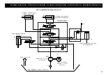
Fig.25

Fig.26

Summary of Contents for S 561

Page 1: ...nales INSTALLATION BEDIENUNG UND WAR TUNG Originalbetriebsanleitung MANUAL DE INSTRUCCIONES Manual de instrucciones original SMONTAGOMME UNIVERSALE PER SERVIZIO MOBILE UNIVERSAL TRUCK TYRE CHANGER FOR...

Page 2: ...REINSTIMMUNG DECLARACION CE DE CONFORMIDAD al quale questa dichiarazione si riferisce E CONFORME ALLE SEGUENTI DIRETTIVE to which declaration refers is in conformity with the FOLLOWING DIRECTIVES au q...

Page 3: ...et und 2003 108 CE RAEE e le disposizioni di Legge del Paese di destinazione della macchina apparecchiatura as well as with the national laws in force in the Country of Installation ainsi qu aux lois...

Page 4: ...ucteur ou les revendeurs autoris s This equipment is subject to the regulations foreseen by Directives 2002 96 CE and 2003 108 CE RAEE and therefore it cannot be scrapped as a generic scrap material b...

Page 5: ...TIFIC DES SIGNAUX DE DANGER 10 IDENTIFICATION DES COMMAN DES 11 POSITION DE TRAVAIL 12 CONTROLE DU BON FONCTIONN 13 UTILISATION 13 1 Blocage de la roue Blocage des jantes en alliage 13 2 Roues tubeles...

Page 6: ...achine for straightening rims breaking beads of still inflated or dirty tyres turning rasping cutting tyres The Manufacturer shall not liable for any injury to persons or damage to things caused by im...

Page 7: ...on Personal benutzt werden das speziell angeleitet wurde und dazu eine Genehmigung hat Ein Bediener wird als qualifiziert bezeichnet wenn er die im vom Hersteller bereitgestellten Bedienungs und War t...

Page 8: ...ive headphones they shall NOT wear any form of clothing that could get caught up or restrict the operator s movements The operator must be able to read and understand the danger warnings understand th...

Page 9: ...as de besoin Le d monte pneu ne doit en aucun cas tre utilis par des personnes souffrant d un quelconque handicap dans le cas o cela compromettrait la s curit durant l utilisation Toute intervention n...

Page 10: ...na viene fornita fissata sul pallet con gabbia in legno Lo smontagomme deve essere trasportato nell imballo originale e mantenuto nella posizione indicata sull imballo stesso Lo spostamento della macc...

Page 11: ...u dans la position indiqu e sur ce dernier le d placement de la machine dans on emballage doit s effectuer avec un chariot l vateur de port e appropri e en pla ant les fourches hauteur dans les points...

Page 12: ...nstallation is outdoor it must be protected by some kind of roofing against rain The following work environment conditions are applicable Relative humidity from 30 95 without condensation Temperature...

Page 13: ...la m quina permanezca estable y permita a los rodillos de la pedana correr libremente Si la m quina se instala en un lugar abierto es necesario protegerla de la lluvia con una marquesina Las condicion...

Page 14: ...dimensions minimum de 1100 x 1600 H mm Hauteur au sol du plan d installation de 500 700 mm Liste indicative de mod les de fourgonnettes permettant l installation il incombe au client de s assurer de l...

Page 15: ...e rendendo l utilizzo pericoloso In base al tipo di furgone in possesso occorre determina re adeguati sistemi di fissaggio in maniera da bloccare in modo sicuro lo smontagomme al furgone stesso The ty...

Page 16: ...B 1 sa position doit tre telle que la ridelle lat rale puisse tre ferm e correctement sans heurter le d monte pneu Fixer le d monte pneu hauteur de 4 points minimum au plateau du v hicule en effectuan...

Page 17: ...15 B 1 Min 1100 mm Min 1600 mm...

Page 18: ...re della centralina oleodinamica sia quello indicato dalla freccia 6 fig B 3 In caso contrario fare invertire tra loro da personale specia lizzato due fili nella spina del cavo di alimentazione CONTRO...

Page 19: ...er sich aus der Nichtbeachtung dieserAnweisungen ergibt enthebt den Hersteller von jeder Haftung und f hrt zum Verfall des Garantieanspruchs Arbeiten an der elektrischen Anlage auch kleineren Umfangs...

Page 20: ...e apporre al di fuori del furgone un lampeg giante di pericolo arancione D E Durante l utilizzo dello smontagomme con gruppo elet trogeno avviato e compressore in funzione CONSI GLIABILE indossare una...

Page 21: ...acer la cl en position 1 de chauffage et une fois le t moin jaune allum placer la cl sur la position 2 pour la mise en marche L op ration de mise en marche du groupe g n rateur compresseur doit tre co...

Page 22: ...ispetto al motore fig B9 Seguire correttamente le fasi descritte sopra per evitare manovre pericolose o danni alle parti dello smonta gomme C D F B 6 B 7 B 8 B 9 PUTTING THE MACHINE AWAY Once you have...

Page 23: ...sitif auto centrant faire pivoter le dispositif auto centrant et placer une griffe en position perpendiculaire au moteur lectrique du mandrin fig B 8 l aide du levier 8 fig C page 20 placer le bras po...

Page 24: ...sere raccolti 1 Gruppo elettrogeno 2 Braccio porta autocentrante 3 Autocentrante 4 Piede di appoggio 5 Consolle di comando 6 Utensile a rullo 7 Comando movimento destra sinistra carrello 8 Comando sal...

Page 25: ...le from moving parts of the machine Neck laces bracelets and too large clothes can be dangerous for the operator 1 Stromerzeugungsaggregat 2 Spannfuttertragearm 3 Spannfutter 4 St tzfu 5 Bedienkonsole...

Page 26: ...cante di una o pi targhette di pericolo Non interporre oggetti che ne ostrui scano la visione all operatore Per eventuali richieste utilizzare il codice indicato nella presente tavola 3005419 3005423...

Page 27: ...add any object that could prevent the operator from seeing the labels Use the code in this table to order labels you need ATTENTION Si les plaques signal ti ques de danger sont peu lisibles ou si elle...

Page 28: ...column fig C enables the operator to work in any position around the machine whichever is most convenient on a case to case basis On this mobile control column the following controls are located The...

Page 29: ...diqu par les fl ches plac es sur la p dale Sur le d monte pneu sont galement mont s La poign e 15 Fig D qui permet de basculer le bras porte outil 14 Fig D de la position de travail la position hors s...

Page 30: ...entrante 3 Fig C1 deve ruotare in senso orario premere il pedale a bilanciere sul lato sinistro l autocentrante deve ruotare in senso antiorario 3 Depress the right pedal 10 Fig C the spindle 3 Fig C1...

Page 31: ...c t gauche le mandrin doit tourner dans le sens inverse Por tanto antes de todo accionar la manilla 15 Fig D para colocar el brazo en esta posici n ATENCI N El descenso del brazo porta tiles crea punt...

Page 32: ...g C1 in posizione chiusa avvicinare la ruota all autocentrante agire sulla leva 9 fig C per aprire l autocentrante e bloccare cos il cerchio internamente e nella posizione pi conve niente che va scelt...

Page 33: ...r au sol et les sou lever l aide d un moyen de levage m canique appropri 3 Relever ou abaisser le bras de fa on centrer au mieux le mandrin auto centrant 3 fig C1 par rapport la jante 4 Avec les griff...

Page 34: ...cerchi in lega 138 90 BLOCCAGGIO CERCHI IN LEGA ATTENZIONE Non abbandonare il posto di lavoro con la ruota bloccata sull autocentrante e sollevata da terra LIGHT ALLOY RIM LOCKING The 137 90 clamps es...

Page 35: ...ndommager Les griffes 137 90 se fixent ba onnette sur le support de la griffe du mandrin voir figure E 7 Gr ce une vis oreilles les griffes peuvent tre bloqu es sur le support Bloquer la jante de la m...

Page 36: ...le evitare di com piere l operazione 6 per passare da un tallone all altro Agganciando il braccio portautensile nella posizione di lavoro cen trale X possibile dopo aver sollevato il pneumatico trasla...

Page 37: ...pen verlegen und in zweiter Arbeitsstellung wieder festmachen Die H nde nicht auf dem Werkzeug halten wenn es inArbe itsstellung wiedergestellt wird um m gliche Quetschungen zwischen Werkzeug und Rad...

Page 38: ...mantenere in equilibrio la ruota Le ruote non devono mai essere sollevate dall operatore si deve farle rotolare sul pavimento per ruote pesanti oltre 110 kg e o di grandi dimensioni diametro oltre 130...

Page 39: ...efindet Erster Wulst soll in Stellung getreten sein Abb 25 8 Rollenwerkzeug 4 5 mm fern von Felge stellen und auf den zweiten Reifenwulst dr cken um die Zange einzuf gen Abb 25 9 Rechts drehen indem s...

Page 40: ...sia il carter riduttore che il serbatoio centralina sono dotati di appositi tappi di scarico To ensure that this tyre changer works perfectly over the years carry out the routine maintenance schedule...

Page 41: ...nachf llen ISO L HV VG46 Persian Oil Idrol T oder gleichwertige Sorten Bsp Esso Invarol EP Agip Arnica Mobil DTE 15 Fina Hydran HV Shell Tellus T Total Equivis ZS Castrol Hyspin AWH HV BP Bactram HV C...

Page 42: ...the mains electric supply REMEDIES PROBLEMA PROBLEM After having switched the general button on the general warning light also switches on but the motor on the hy draulic power pack does not function...

Page 43: ...aufen zu bringen oder wenn St rungen irgendwelcher Art vorliegen verwenden Sie die Maschine NICHT sondern verst ndigen umgehend den technischen Kundendienst ST RUNGEN 1 Den Stecker richtig in die Netz...

Page 44: ...con un cappuccio in nylon Nel caso di rimessa in uso dopo un periodo di accantonamento sar necessario Inserire nuovamente i liquidi di funzionamento nei serbatoi If the machine has to be stored for a...

Page 45: ...eb erforderliche Fl ssigkeiten enthalten und die ganze Maschine vor Staub sch tzen indem man sie mit einer Nylonhaube abdeckt Wenn die Maschine sp ter wieder in Betrieb genommen werden soll ist folgen...

Page 46: ...ne della macchina riportante 1 Dati del costruttore 2 Modello 3 Numero di serie 4 Fase 5 Voltaggio 6 Frequenza 7 Assorbimento 8 Anno di costruzione 9 Peso della macchina 10 Potenza assorbita The manuf...

Page 47: ...el Vereinfacht die Montage der W lste bei Schlauchreifen 20 ZUBEHOER 19 Auf der R ckseite der Maschine befindet sich das Typenschild der Maschine auf dem folgende Angaben stehen 1 Herstellerdaten 2 Mo...

Page 48: ...03 04 PRESA VOLANTE 3Ph N T GW62009 cod MCC0459 PE MOTORE POMPA 3PH 230 400V 50 60HZ 2HP B5 cod 4596777 L 2 5 m L 7 m L 3 m L 2 m 7 71 2x1mmq L 2 m Cod 4596726 NO Cod 4595082 NC Cod 4595082 NC 5x1mmq...

Page 49: ...LICO FILTRO MOT 3PH 230 400V 50 60HZ 1 5 1 8 KW cod 4596777 POMPA GR 1 4 8 cc giro cod 4195706 SERBATOIO OLIO CILINDRO APERTURA CHIUSURA AUTOCENTRANTE CILINDRO RIBALTAMENTO MACCHINA CILINDRO SALITA DI...

Page 50: ...GIULIANO INDUSTRIAL S p A Via Guerrieri 6 42015 CORREGGIO ITALY Tel 39 522 73 11 11 Fax 39 522 63 31 09 E mail info giuliano automotive com http www giuliano automotive com...

Reviews:

Related manuals for S 561