Heat pump water heater
- 35 -
EN
We recommend that you install the equipment close to the main hot water drawing point, to prevent heat dispersions
along pipes, and if possible near a drain, for easier emptying and condensate discharge. The hydraulic connection of
the equipment is shown in Fig. 3. The paragraphs below describe the proper installation procedure.
3.2.1
Hydraulic safety unit
(mandatory)
You must install an hydraulic safety unit (not supplied) complying with EN 1487 or with equivalent standards in
force; it must include at least the following components:
•
Shut-off valve;
•
Check valve;
•
Check valve control device;
•
Safety valve;
•
Hydraulic load interrupting device.
The above components are required to safely run the supplied equipment. The rated calibration pressure of the
hydraulic safety unit mus be of 0.6 MPa (6 bar). Pay attention while installing the hydraulic safety unit, avoiding to
force or alter it. Water may drip from the hydraulic safety unit discharge connector (see paragraphs “USAGE
INSTRUCTIONS (user) - Water dripping from the hydraulic safety unit”). This opening must be left exposed to the
atmosphere. You need to install a discharge pipe, with a constant downward slope, in a condensate- and ice-free
area. There must be no obstructions in the pipe, to avoid overpressures.
3.2.2
Pressure reducer
Should the network pressure exceed 0.5 MPa (5 bar), you need to install an appropriate pressure reducer (Fig. 3 ref.
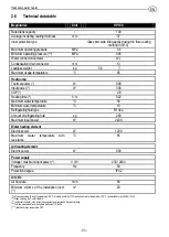
4) upstream of the hydraulic safety unit, ensuring the indicated operating range. ( please refer to the technical data
table)
3.2.3
Expansion tank
To prevent any overpressures that might damage the equipment, frequently triggering the safety unit and causing
water dripping, it is mandatory that you install an expansion tank (Fig. 3 ref. 1) having a capacity equal to 10% of
the rated capacity of each heating equipment. Install it in accordance with the instructions provided by the
manufacturer. The expansion tank is required to keep pressure constant and avoid harmful pressure shocks or
accidental overpressures.
3.3
Unit filling
WARNING: Switching on the equipment when it is not filled with water will seriously damage the
refrigerating units and the electrical resistance.
WARNING: In the presence of water with a hardness degree >20°TH (where 1°TH=French
degree=10mg CaCo3/l) it is mandatory that you install a softener to reduce limestone scaling inside
the boiler and keep the electrical resistance and the hydraulic safety unit in good working order.
To fill the equipment you need to:
•
turn the hydraulic unit cock (Fig. 3 ref. 3) to the operating position; opening the cock enables equipment
supply. The retaining device incorporated in the hydraulic safety unit prevents hot water from returning;
•
open the main water supply or the equipment water supply cock;
Summary of Contents for Futura 100 TS
Page 2: ... 2 ...
Page 23: ...Scaldacqua a pompa di calore 23 IT Fig 3 Fig 4 ...
Page 24: ...Scaldacqua a pompa di calore 24 IT ...
Page 44: ...Heat pump water heater 44 EN 8 Illustrations Fig 1 Fig 2 Distances from any surface ...
Page 45: ...Heat pump water heater 45 EN Fig 3 Fig 4 ...
Page 46: ... 46 APPUNTI NOTES ...
Page 47: ... 47 ...


