background image

1  Introducing Your Notebook

1-8

1.1.9  Wireless Communication Switch 

Turns the wireless communication function on or off. The wireless communication LED on 

the front panel lights when the function is activated. 

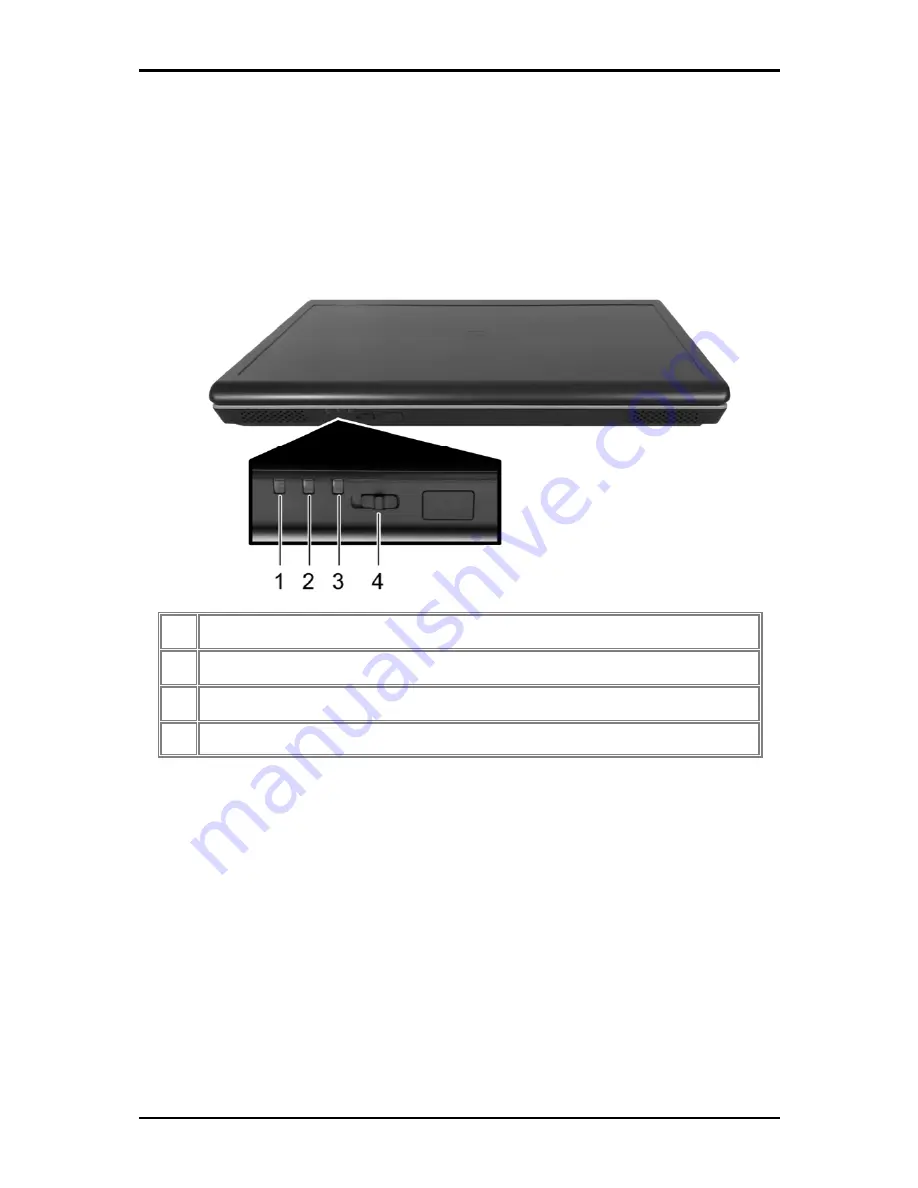
1.1.10  Device Status Indicators / Power Status 

The LEDs on the front of notebook indicate the device and power status. 

Power On (Blue) 

Battery Charge (Blue/Amber) 

Bluetooth (Amber)/Wireless (Blue) 

Wireless Communication Switch 

The flashing Power On LED indicates the notebook is in standby mode. 
For detailed battery status, see 

2.4 Battery. 

Summary of Contents for W536M

Page 1: ......

Page 2: ......

Page 3: ...he manual from the beginning to end Simply find your way to the section that interests you using the table of contents or browse through the manual You will come across the following icons in this manual Helpful pointers and tricks to get more from your notebook To help you note and avoid possible damage to your notebook s hardware or software or loss of your work Points out possible damage to pro...

Page 4: ......

Page 5: ...ation Switch 1 8 1 1 10 Device Status Indicators Power Status 1 8 1 2 Right Side 1 9 1 2 1 Optical Media Drive 1 10 1 2 2 USB Port 1 10 1 2 3 AC Adapter Connector 1 10 1 3 Left Side 1 11 1 3 1 VGA Port 1 12 1 3 2 LAN Jack 1 12 1 3 3 Modem Jack 1 12 1 3 4 S Video out Port 1 12 1 3 5 High Power USB Port 1 12 1 3 6 IEEE 1394 Port 1 12 1 3 7 New Card Slot For Express Card 1 13 1 3 8 Multiple Digital M...

Page 6: ...ng a Battery 2 10 2 4 8 Storing a Battery 2 10 2 4 9 Working With Extra Battery Packs 2 10 2 4 10 Maximizing Battery Life 2 10 2 5 Advanced Charging Functions Q Charging Power USB Buttons 2 11 2 5 1 Q Charging Button with Smart Battery Software 2 11 2 5 2 Using the Q Charging Button 2 12 2 5 3 Using the Power USB Button 2 12 2 6 WOW Video Audio 2 13 2 6 1 Installing the Software 2 13 2 6 2 Using t...

Page 7: ... through the BIOS Setup Program 4 2 4 2 1 Accessing the BIOS Setup Program 4 3 4 2 2 Launching Submenus 4 4 4 2 3 Saving Changes and Exiting the Setup Program 4 4 4 3 The Main Menu 4 5 4 4 The Advanced Menu 4 7 4 5 The Security Menu 4 8 4 6 The Boot Menu 4 12 4 7 The Exit Menu 4 13 Chapter 5 Troubleshooting 5 1 Frequently Asked Questions 5 1 Appendix A Recovery Update Notices Appendix B Service Ce...

Page 8: ...he electrical outlet or from any other type of external power source such as an external battery Do not operate the computer near water for example near a bathtub kitchen sink or laundry tub in a wet basement by a swimming pool or in the rain Do not connect or disconnect any cables or perform maintenance or reconfiguration of this product during an electrical storm Avoid using the wired modem or L...

Page 9: ...se an extension cord with your AC adapter ensure that the total ampere rating of the products plugged into the extension cord does not exceed the ampere rating of the extension cable When using your power cord make sure to position it around objects so it will not be cut or punctured When you disconnect a cable pull on its connector on its strain relief loop not on the cable itself As you pull out...

Page 10: ...hort circuit the battery terminals The resulting excessive current flow can cause extremely high temperatures and may result in damage from burns Danger of explosion may occur if battery is incorrectly replaced Replace only with the same or equivalent type battery recommended by the manufacturer Do not dispose of batteries in a fire They may explode Check with local authorities for disposal instru...

Page 11: ...If the battery pack leaks gives off a bad odor generates heat becomes discolored or deformed or in any way appears abnormal during use recharging or storage immediately remove it from the computer or charger and stop using it ...

Page 12: ...being hazardous to the environment Internal Modem Warnings CAUTION When using your telephone equipment basic safety precautions should always be followed to reduce the risk of fire electric shock and injury to persons including the following The modem cable you connect to your computer should have a minimum wire size of 26 AWG American wire gauge and an UL compliant RJ 11 modular plug Avoid using ...

Page 13: ...ne company may make changes to facilities equipment operations or procedures that could affect the proper functioning of your equipment If they do you will be notified in advance to give you an opportunity to maintain uninterrupted telephone service If this equipment should fail to operate properly disconnect the equipment from the phone line to determine if it is causing the problem If the proble...

Page 14: ...y 7 Do not allow anything to rest on the power cord Do not locate this product where people will step on the cord 8 If an extension cord is used with this product make sure that the total ampere rating of the equipment plugged into the extension cord does not exceed the extension cord ampere rating Also make sure that the total rating of all products plugged into the wall outlet does not exceed th...

Page 15: ...ncy energy and if not installed and used in accordance with the instructions may cause harmful interference to radio communications However there is no guarantee that interference will not occur in a particular installation If this equipment does cause harmful interference to radio or television reception which can be determined by turning the equipment off and on the user is encouraged to try to ...

Page 16: ... Declaration of Conformity BSMI Notice Taiwan Only Most Compal computer products are classified by the Bureau of Standards Meteorology and Inspection BSMI as Class B information technology equipment ITE This marked on the product indicates the product complies with the BSMI standard ...

Page 17: ...tected by methods and claims of certain U S patents and other intellectual rights owned by Macrovision Corporation and other rights owners Use of this copyright protection technology must be authorized by Macrovision Corporation and is intended for home and other limited viewing uses only unless authorized by Macrovision Corporation Reverse engineering or disassembly is prohibited ...

Page 18: ...ory Two SO DIMM with 512MB 1GB 2GB modules Upgradable to 4GB memory by two SO DIMM Easy install from bottom side Display Supports 15 4 WXGA 1280 x 800 TFT color LCD Keyboard ENE 925Q K B controller 86 US 87 UK 88 JA Key 12 function keys 4 cursor keys Windows key Application keys 19 05mm pitch 2 5mm stroke H 5 1mm Hard Disk Drive HDD 9 5mm height 2 5 HDD Up to 160GB capacity Supports SATA 1 5Gb s 5...

Page 19: ...C in jack x 1 RJ 45 jack x 1 RJ 11 jack for 56Kbps V 92 Modem US Canada UK Germany French optional 3 in 1 card reader for SD MMC MS optional Single Wide New Card slot 54mm type x 1 Kensington lock WLAN PCI Express base specification compliant 802 11 a b g n Intel WLAN card Modem Internal Modem with MDC solution MDC1 5 optional Bluetooth Foxconn Bluetooth V2 0 EDR Broadcom chipset optional Mini Car...

Page 20: ... Low battery alarm beep Auto backlight off when LCD cover closed Full ACPI 2 0 supported LCD Auto DIM mode by time out Easy Buttons Power button Internet access button E mail button Wow Video Wow Audio buttons Mute button AC Adapter Universal AC adapter 100 240V AC 50 60Hz 65W with 19V DC output 3 pin type for AC in Memory Card SO DOMM Socket optional 3 in 1 Card Reader MS SD MMC Push push type wi...

Page 21: ...1 Chapter 1 Introducing Your Notebook ...

Page 22: ...he notebook 1 Internal Speakers 8 Keyboard 2 Built in Microphone 9 Touch Pad 3 Display 10 Touch Pad Buttons 4 Power Button 11 Consumer Infrared Receiver optional 5 Easy Buttons 12 Wireless Communication Switch 6 Status LEDs 13 Device Status Indicators Power Status 7 Power USB Q Charging Buttons ...

Page 23: ...ed and turned on the image may appear on either the display or the external device Alternatively you can press to switch the video image to the display only the display and the external device simultaneously or the external device only 1 1 3 3 Setting the Display Resolution To view a program at a specific resolution both the video controller and display must support the program and the necessary v...

Page 24: ...ton while on In Windows Vista you can configure this in Control Panel System and Maintenance or Hardware and Sound Power Options Change plan settings Change advanced power settings Easy Buttons The notebook offers these buttons for quick launch programs and functions Internet access button Email button Wow Video Wow Audio Wow Video Audio Mute button Keyboard Indicators HDD access indicator Num Loc...

Page 25: ... keypad press The indicator will light when the numeric lock is on To disable the numeric keypad press again To use the primary function of a dual function key when the numeric keypad is enabled press and the desired key 1 1 6 2 Keyboard Shortcuts Sleep Wireless Bluetooth On Off To enable this function you need to install Wireless Select Switch Switches Display Mode LCD CRT TV LCD CRT Simultaneous...

Page 26: ...nd Fast Forward Number Lock Scroll Lock Caps Lock 1 1 6 3 Windows Logo Key Functions Opens Windows Explorer Opens the Run dialog box Opens the Search Results dialog box Opens the Search Results Computers dialog box when your notebook is connected to a network Opens the System Properties dialog box ...

Page 27: ...nction as mouse buttons Clicking these buttons makes selections drags objects or performs a variety of other functions depending on the software To select an object first move the pointer over the object you want to select and then press the left button one time and release it The functionality of these buttons depends on your software Double clicking is a common technique for selecting objects or...

Page 28: ...1 Introducing Your Notebook 1 7 1 1 8 Touch Pad Buttons The left and right touch pad buttons perform the same functions as the left right buttons of a standard mouse ...

Page 29: ...ights when the function is activated 1 1 10 Device Status Indicators Power Status The LEDs on the front of notebook indicate the device and power status 1 Power On Blue 2 Battery Charge Blue Amber 3 Bluetooth Amber Wireless Blue 4 Wireless Communication Switch The flashing Power On LED indicates the notebook is in standby mode For detailed battery status see 2 4 Battery ...

Page 30: ...1 Introducing Your Notebook 1 9 1 2 Right Side The following picture shows the right side of the notebook 1 Optical Media Drive 2 USB Ports 3 AC Adapter Connector ...

Page 31: ...s data transfer rates up to 480 Mbps USB peripherals have a single standard for cables and connectors You can install and remove USB devices while the computer is on This is called hot swapping 1 2 3 AC Adapter Connector Use this connector to attach the AC adapter to your notebook You can connect an AC adapter when your notebook is switched on or off While the AC adapter works with electrical outl...

Page 32: ...e The following picture shows the left side of the notebook 1 VGA Port 2 LAN Jack Green Amber 3 Modem Jack 4 S Video out Port 5 High Power USB Ports 6 IEEE 1394 Port 7 New Card Slot 8 Multiple Digital Media Slot 9 Microphone Jack 10 Headphone Jack ...

Page 33: ...you to connect the notebook to a telephone line with a standard RJ 11 connector 1 3 4 S Video out Port The S Video out port allows you to connect an external display device like a TV set or device which has S video port to the notebook 1 3 5 High Power USB Port High power USB ports can provide power for devices that draw more than 100mA from the bus line such as cameras and external hard disks 1 3...

Page 34: ...e cards when your notebook is running The card will be detected automatically when installed Usually Express Cards have a mark or symbol to show which end to insert into the slot Insert the card according to the orientation symbol and slide the card into the slot Check the documents that came with your card if the orientation is unclear 1 Press to release the dummy card from the New Card slot 2 Ho...

Page 35: ...quipment 1 3 8 1 Adding and Removing SD MMC MS Cards Before removing an SD MMC MS card stop it running from the configuration utility on the taskbar Failure to do so could result in data loss Insert the SD MMC MS card into the card reader slot To remove the SD MMC MS card push it in gently it ejects automatically 1 3 9 Audio Ports You can connect a headphone or an external speaker to the port and ...

Page 36: ...1 Introducing Your Notebook 1 15 1 4 Rear Side The following picture shows the rear side of the notebook Kensington Lock ...

Page 37: ...cing Your Notebook 1 16 1 5 Bottom Side The following picture shows the bottom side of the notebook 1 Battery Pack 2 Battery Release Latch 3 HDD Cover 4 Battery Lock Switch 5 Thermal Cover 6 Memory Module Cover ...

Page 38: ...re details see 2 4 Battery To remove the Battery Pack 1 Move the Battery Lock Switch to the right Unlock position 2 Slide the Battery Release Latch to the left and gently pry the Battery Pack from the computer chassis 1 5 2 Battery Release Latch The Battery Release Latch secures the battery pack To release slide the latch and then remove the battery pack from the bay ...

Page 39: ...odule in the second slot matching up the notch along its connector rim with the tooth in the connection slot 5 When the module is secured press down gently until it snaps into place Depending on how much additional memory you require you may need to replace the original memory module To remove a memory module 1 Make sure the computer is turned off 2 Remove the two screws securing the memory module...

Page 40: ......

Page 41: ...2 Chapter 2 Operating Your Notebook Vista ...

Page 42: ...you are working at home or while traveling you need a dial up connection Ask your system administrator for the telephone number of the network To set up the connection go to Start Control Panel Network and Internet Network and Sharing Center Click Set up a connection or network on the left pane of the Network and Sharing Center window Choose a connection option and follow the on screen instruction...

Page 43: ...vies click Help on the CD player software or DVD player software 2 2 2 Adjusting the Volume If you do not hear anything when playing a CD or DVD check that the speakers are not muted Start All Programs Accessories Windows Mobility Center In the Windows Mobility Center window click and drag the bar in the Volume column and slide it left or right to decrease or increase the volume Audio Volume Down ...

Page 44: ...2 Operating Your Notebook Vista 2 3 Click the pull down menu under Colors select Medium 16 bit and click OK ...

Page 45: ...ttings Expand the Power buttons and lid category to configure the settings When leaving your notebook unattended for long periods place it in standby or hibernate mode You can exit either power management mode by pressing the power button 2 3 2 Power Management Modes 2 3 2 1 Sleep Mode This mode conserves power by switching off the hard drive and display after a preset period of inactivity a time ...

Page 46: ...tton Start X Hibernate The settings can be accessed via Power Options Advanced settings window See 2 3 1 Managing Your Notebook s Power To exit Hibernate mode press the power button You cannot exit Hibernate mode by pressing a key or the Touch Pad 2 3 3 Power Options Properties To access the Windows Power Options window Start Control Panel System and Maintenance Power Options 2 3 3 1 Select a powe...

Page 47: ...ess the power button Set the computer to Do nothing Sleep Hibernate Shutdown when you close the laptop lid Select the password requirement when the computer wakes from sleep 2 3 3 3 Create a power plan Besides the three preset power plans offered in Windows Vista you can also customize your own power plan Select Create a power plan on the left pane of the Power Options window to begin configuring ...

Page 48: ...l providing optimal performance You can also individually alter and save each of these settings and schemes if desired Choose from the following three power plans that best describes the desired relationship between power and performance Windows Vista automatically chooses the SpeedStep mode to find the most appropriate speed for your processor according to the type of plan you choose and your cur...

Page 49: ... never be disposed of with household waste Contact your local waste disposal or environmental agency for advice on disposing of used lithium ion batteries Only use the SQU 528 SQU 601 ID6 ID6 2600 IDST 9 CBPIL48 CBPIL52 or CBPIL73 battery pack with this computer 2 4 2 Checking the Battery Charge Battery Status Indicator behavior Charging Flashes blue Fully Charged Solid blue Critical Low Amber app...

Page 50: ...ry s internal circuitry prevents the battery from overcharging Before using the battery for the first time it must be charged Connect the computer to an electrical outlet and allow the battery to fully charge indicated by the battery indicator light on the front panel of the notebook Once a battery pack is fully charged for the first time use your notebook on battery power until the battery discha...

Page 51: ... you spend a lot of time traveling working without connecting your notebook to an electrical outlet it may be a good idea to carry additional battery packs so you can quickly replace a discharged battery and continue working 2 4 10 Maximizing Battery Life A battery can be recharged many times but over time it will lose its ability to hold a charge To maximize battery life If you are not using your...

Page 52: ...boot 2 5 1 2 Using the Software Before you can use the Q Charging button you must first configure the Smart Battery software You can access the software via the Control Panel 1 Click Start Settings Control Panel 2 Double click the Smart Battery icon The main screen appears v Check to display the smart battery icon in the system tray Click to close window Click to apply default settings Click to ap...

Page 53: ...ptor DO NOT disconnect the AC adaptor as this may cause irreversible damage to your battery and laptop 2 5 3 Using the Power USB Button The laptop is equipped with a power USB function which allows you to increase the power output when charging an external USB device such as a mobile phone or PDA Press the Power USB button to increase the power output to 1 ampere When not pressed power output is 0...

Page 54: ...o cycle through the available modes Theater Office Photo Normal User Define see 2 6 3 Changing Software Settings for details Press the Wow Audio button on the front of the laptop to select the preferred audio mode Press the button repeatedly to cycle through the available modes Flat Classic Speech Pop 2 6 3 Changing Software Settings You can configure the Wow Video Audio software via the Control P...

Page 55: ...3 Chapter 3 Caring for Your Notebook ...

Page 56: ...ook down turn it off and disconnect it from the electrical outlet and any external devices such as a printer Remove the battery pack Use a slightly moistened soft lint free cloth to wipe your notebook s display Use only water or a recommended computer cleaner 3 1 3 Cleaning the Touch Pad Shut your notebook down turn it off and disconnect from the electrical outlet and any external devices such as ...

Page 57: ...it is reading from or writing to a disk may damage the disk the drive or both Keep your notebook and disks away from objects that generate strong magnetic fields such as stereo speakers Information on disks is stored magnetically Placing a magnet too close to a disk can erase important files Scan all new files for viruses This precaution is especially important for files you receive via email disk...

Page 58: ...case Avoid packing the computer with items such as shaving cream colognes perfumes or food Protect the computer the batteries and the hard drive from hazards such as extreme temperatures dirt dust liquids or overexposure to sunlight Pack the computer so that it does not slide around in the trunk of your car or in an overhead storage compartment When traveling by air never check in your notebook as...

Page 59: ...ters When traveling by air ensure that you have a charged battery available in case you are asked to turn on the computer Before you use the computer on an airplane verify that such usage is permitted Some airlines forbid the use of electronic devices during the flight All airlines forbid the use of electronic devices during takeoff and landing Never walk your notebook through a metal detector Sen...

Page 60: ......

Page 61: ...Chapter 4 The BIOS Setup Program ...

Page 62: ...Video display options Password protection from unauthorized use Boot devices The settings made in the Setup program intimately affect how the notebook performs It is important therefore to first understand all the available options and second to make settings appropriate for the way you use the notebook This chapter guides you through the Setup program by providing clear explanations for all Setup...

Page 63: ...e will inform you of any errors or invalid settings and prompt you to run the Setup program to correct the problem Even if you are not prompted by a message instructing you to use the Setup program at some time in the future you may want to change the configuration of your computer For example you may want to make changes to the display option settings or enable the notebook s password function fo...

Page 64: ... Memory 1022 MB BIOS Version XXXXX Language English US F1 Help Select Item F5 F6 Change Values F9 Setup Defaults Esc Exit Select Menu Enter Select 4 Sub Menu F10 Save and Exit The Menu Bar The top of the Setup screen has a menu bar with the following selections Main Allows the user to configure standard IBM PC AT system parameters Advanced Allows the user to configure advanced system settings Secu...

Page 65: ... Submenus A submenu contains additional options for a field parameter To call up a submenu simply move the highlight to the desired field and press the Enter key The submenu opens If you are a first time user or are not familiar with BIOS Setup program it is highly recommended that you take a few minutes to familiarize yourself with each of the submenus and their corresponding functions If you acc...

Page 66: ...xtended Memory 1022 MB BIOS Version XXXXX Language English US F1 Help Select Item F5 F6 Change Values F9 Setup Defaults Esc Exit Select Menu Enter Select 4 Sub Menu F10 Save and Exit System Time and System Date The hour is displayed with 24 hour format The values set in these two fields take effect immediately Hard Disk The hard disk information is displayed with the manufacturer and model name Qu...

Page 67: ...ended memory with an integer in the system but 32Bit SMI will occupy 1 MB and UMA frame buffer Integrated VGA uses only Extended Memory size Total memory size 1 MB 1 MB UMA frame buffer BIOS Version This field displays current version of the BIOS Language Currently only English is supported ...

Page 68: ...MB Legacy USB Support Enabled Enhanced AHCI WinXP SP1 IAA driver supports AHCI mode F1 Help Select Item F5 F6 Change Values F9 Setup Defaults Esc Exit Select Menu Enter Select 4 Sub Menu F10 Save and Exit AHCI Advanced Host Configuration Interface Configuration Disabled Disables the AHCI mode Enabled Enables the AHCI mode Total Graphics Memory This field displays the total onboard graphics memory ...

Page 69: ...hanumeric characters a z 0 9 and be eight characters in length NOTE The supervisor password must be set before the user password can be set Set Supervisor Password Set User Password Phoenix TrustedCore tm Setup Utility Main Advanced Security Boot Exit Item Specific Help Supervisor Password Is Clear User Password Is Clear Set Supervisor Password Enter Supervisor password controls access to the setu...

Page 70: ...sword Confirm New Password If there is an existing password then setup will prompt with the following window instead and the current password will be required to be entered at first Set Supervisor Password Enter Current Password Enter New Password Confirm New Password User can type password in field of Enter New Password and re enter password in field of Confirm New Password for verification If ve...

Page 71: ... shows the message While this field is highlighted press Enter The following message is shown Set HDD Master Password Enter New Password Confirm New Password If there is an existing password then setup will prompt with the following window instead and the current password will be required to be entered at first Set HDD Master Password Enter Current Password Enter New Password Confirm New Password ...

Page 72: ... on boot is required the password must be set otherwise it cannot be enabled The formats of the password are as follows Length No more than 8 characters Characters Alphanumeric keys only The shift status Ctrl Shift Alt and Capital are ignored ...

Page 73: ...OM in module bay Phoenix TrustedCore tm Setup Utility Main Advanced Security Boot Exit Item Specific Help HDD Hard Disk Model name CD DVD CD DVD Drive Model name FDD LAN Keys used to view or configure devices Up and Down arrows select a device F5 and F6 moves the device up or down Shift 1 enables or disables a device F1 Help Select Item F5 F6 Change Values F9 Setup Defaults Esc Exit Select Menu En...

Page 74: ...Exit Saving Changes Allows the user to save changes to CMOS and reboot system The following message prompts the user to confirm after pressing Enter on the item Setup Confirmation Save configuration changes and exit now Yes No Yes Exit SETUP and reboot No Go back to previous screen Exit Discarding Changes Allows the user to exit Setup without saving changes to CMOS The following message prompts th...

Page 75: ...e user loads default values in CMOS Setup The following message prompts the user to confirm after pressing Enter on this item Setup Confirmation Load default configuration now Yes No Select Yes to confirm or No to abort You will then return to the setup screen ...

Page 76: ......

Page 77: ...5 Chapter 5 Troubleshooting ...

Page 78: ... refer to your Windows documentation Q The dial tone volume of the internal fax modem is too low How can I increase its volume Go to Start Control Panel Sounds Speech and Audio Devices under Device volume adjust your speaker volume by controlling the volume bar Q What kind of external microphone can I use with my notebook computer You will need to use a self amplifying microphone Q There are echoe...

Page 79: ...val and you cannot unplug or eject your device using Safe Removal 2 In Safely Remove Hardware in the list of devices select the device that you want to unplug or eject and then click Stop This tells the system that you will be unplugging or ejecting the device 3 In Stop a Hardware device click OK A notification appears stating that it is now safe to unplug or eject the device Caution Unplugging or...

Page 80: ......

Page 81: ...6 Appendix A Recovery Update Notices ...

Page 82: ...ry function 2 Right after you see the startup screen such as trademark logo or text the DOS screen will appear Press F9 F9 is a typical hotkey to restore professional settings Please consult with your computer manufacture if your hotkey doesn t function 3 There are three options on the menu RESTORE to restore data ABOUT to display XR2 Lite related information and REBOOT to cancel the recovery and ...

Page 83: ...5 After all the selections have been made the screen shows RESTORE NOW indicating your computer is now recovering the operation system data When the recovery is complete the computer will automatically restart and restore to factory defaults ...

Page 84: ......

Page 85: ...7 Appendix B Service Center ...

Page 86: ... 1 626 854 9338 FAX 1 626 854 9339 WEB Address http www gigabyte us Japan NIPPON GIGA BYTE CORPORATION TEL 81 3 5791 5438 FAX 81 3 5791 5439 WEB Address http www gigabyte co jp China G B T TECH TRADING CO LTD Shanghai TEL 86 21 63410999 FAX 86 21 63410100 GuangZhou TEL 86 20 87586074 FAX 86 20 85517843 Beijing TEL 86 10 62102838 FAX 86 10 62102848 Chengdu TEL 86 28 85236930 FAX 86 28 85256822 Wuha...

Page 87: ... 2 Russia Moscow Representative Office Of Giga Byte Technology Co Ltd WEB Address http www gigabyte ru Germany HAMBURG Representative Office Of Giga Byte Technology Co Ltd TEL 49 40 25330433 ADDRESS BULLENKOPPEL 16 22047 HAMBURG ...

Page 88: ......

Page 89: ...2ZA08G 036M0 Q00 ...

Reviews: