26
PeakStore5 Manual Version 3.0
6.3.1. Preparation
Before the actual balancing process can be started, the vibration sensors and the speed sen-
sor must be applied. A reflection mark must be placed ideally on one of the balancing layers
for the speed measurement. This mark is also the 0° reference position for the later process
that is relevant for applying masses. The speed sensor must be placed with the holder that it
shows directly on the reflection mark. Additionally, the vibration sensors must be placed di-
rectly on the bearing of the balancing layer. Ideally it is placed directly on the housing of the
bearing. The type of the vibration sensor must be chosen that the lower cut off frequency is
below the speed frequency. If configuration type is set to balancing in one layer, the vibration
sensor must be placed on this layer. If balancing in two layers is activated, one vibration sensor
must be placed on each layer. It is necessary to take into account the correct layer for each
vibration sensor, as parametrized in the configuration (see also 6.1.3).
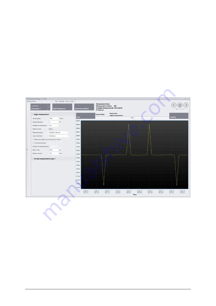
Picture 23: Parameter Balancing Process
Afterwards, the following parameter must be set for the whole balancing process (see also
Picture 23):
•
Target speed:
This speed is used for the whole balancing process. Ideally the balancing
process is done at normal operational speed of the machine. It should be avoided to bal-
ance the machine in the resonance range.
•
Speed tolerance:
The acceptable deviation from the given target speed. A maximum toler-
ance of 50% is allowed.
•
Number of revolutions:
One measurement in the balancing process is done with the given
number of revolutions. It will be automatically rounded to the nearest power of two. The
expected measurement time directly results from the combination of the number of revolu-
tions and the target speed.
•
Balancing target:
The imbalance of the machine can be determined via the measured vi-
bration acceleration or via the inferred vibration velocity.


