4.
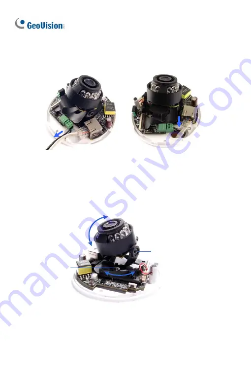
Thread the power and / or network cable(s) through the oval-shaped
hole or the cable opening on the side, and connect the camera to
network and power. For details, see
6.4 Connecting the Camera
.
5.
Secure the Target Mini Fixed Dome to the ceiling or the wall with the
self-tapping screws.
6.
Access the live view. For details, see
24.2 Accessing the Live View
in
the
Quick Start Guide
.
7.
Loosen the tile screw and pan screw, adjust the angles based on the
live view as needed, and tighten the screws again.
Pan Screw
Tilt Screw
8.
Adjust image clarity using the GV-IP Device Utility program. For details,
see
24.3 Adjusting Image Clarity
in the
Quick Start Guide
.
9.
Place the housing cover back and turn to secure it.
50
Summary of Contents for GV-UNP2500
Page 152: ...GV NVR Software DVD Warranty Card Note Power adapter can be purchased upon request 120...
Page 168: ...Pan Adjustment Tilt Adjustment Rotational Adjustment 136...
Page 179: ...Vandal Proof IP Dome Part II 15 15 2 Overview 1 2 3 4 5 6 8 7 9 10 12 11 13 14 147...
Page 189: ...Vandal Proof IP Dome Part II 15 Pan Adjustment Tilt Adjustment Rotational Adjustment 157...
Page 195: ...Vandal Proof IP Dome Part III 16 16 2 Overview 1 2 4 5 3 163...
Page 207: ...Target Vandal Proof IP Dome 17 17 2 Overview 1 2 3 4 5 6 13 12 10 7 8 9 14 11 175...
Page 225: ...Fixed IP Dome 18 Pan Adjustment Tilt Adjustment Rotational Adjustment 193...
Page 253: ...PT Camera 22 22 2 Overview 1 2 3 4 5 6 7 8 9 10 11 12 221...
Page 262: ...M3 Screw x 2 M2 Screw GV IPCAM Software DVD GV NVR Software DVD Warranty Card 230...
Page 263: ...Pinhole Camera 23 23 2 Overview Camera Lens 1 2 3 4 Main Body 6 7 8 9 4 5 231...
Page 279: ...Accessing the Camera 24 6 Unplug the Ethernet cable 247...
Page 284: ...25 The Web Interface 1 2 3 4 5 6 7 8 9 10 11 12 13 252...


