IMPORTANT:
1. Use the supplied ruler and leave about 10 cm of audio, power,
and I/O wires between their connectors and the cable seal.
2. The plugs are used to prevent water from entering the camera
housing. Keep the unused holes plugged and save the
removed plugs for future use.
3. Only thread the wires through their designated holes on the
conduit connector to make sure the wires are properly sealed.
9.
Install the base to the back plate on the wall.
10. Connect the wires to the camera.
A. Install the terminal blocks to the power adapter and I/O devices.
See
Power Connection
and
I/O Device Connections
in
9.5
Connecting the Camera.
B. Install the supplied RJ-45 connector to the Ethernet cable.
C. Plug all the connectors to the camera panel.
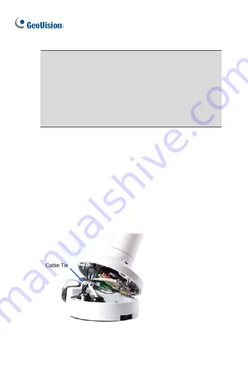
11. Tie the wires with the supplied cable tie and re-install the base to the
camera. You may need to rotate the base for the wires to fit.
84
Summary of Contents for GV-UNP2500
Page 152: ...GV NVR Software DVD Warranty Card Note Power adapter can be purchased upon request 120...
Page 168: ...Pan Adjustment Tilt Adjustment Rotational Adjustment 136...
Page 179: ...Vandal Proof IP Dome Part II 15 15 2 Overview 1 2 3 4 5 6 8 7 9 10 12 11 13 14 147...
Page 189: ...Vandal Proof IP Dome Part II 15 Pan Adjustment Tilt Adjustment Rotational Adjustment 157...
Page 195: ...Vandal Proof IP Dome Part III 16 16 2 Overview 1 2 4 5 3 163...
Page 207: ...Target Vandal Proof IP Dome 17 17 2 Overview 1 2 3 4 5 6 13 12 10 7 8 9 14 11 175...
Page 225: ...Fixed IP Dome 18 Pan Adjustment Tilt Adjustment Rotational Adjustment 193...
Page 253: ...PT Camera 22 22 2 Overview 1 2 3 4 5 6 7 8 9 10 11 12 221...
Page 262: ...M3 Screw x 2 M2 Screw GV IPCAM Software DVD GV NVR Software DVD Warranty Card 230...
Page 263: ...Pinhole Camera 23 23 2 Overview Camera Lens 1 2 3 4 Main Body 6 7 8 9 4 5 231...
Page 279: ...Accessing the Camera 24 6 Unplug the Ethernet cable 247...
Page 284: ...25 The Web Interface 1 2 3 4 5 6 7 8 9 10 11 12 13 252...


