208
To install
GV-Mount211P / 211-2 / 212-2 / 212P / 213 / 502 / 503
on GV-Mount300-2 / 310-2
1.
Assemble the GV-Mount300-2 / 310-2, by attaching the two mounting plates onto the
mounting bracket with the supplied
carriage bolts, 1/4” plain washers, and 1/4” flange
nuts.
2.
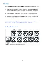
Position and secure
GV-Mount211P / 211-2 / 212-2 / 212P / 213 / 502 / 503 to GV-
Mount300-2 / 310-2 as instructed on the enclosed
Screw Position Chart
.
3.
Secure your GV-IP Camera to the GV-Mount211P / 211-2 / 212-2 / 212P / 213 / 502 /
503 to complete the installation.
Note:
For details on attaching your GV-IP Camera to GV-Mount211P / 211-2 / 212-2 /
212P / 213 / 502 / 503, see optional installations in
Chapter 1 Introduction
.
G. Screw Position Chart
Screws:M4*25
GV-Mount502
GV-TBL2703/4703
GV-ABL2701/4701/2703/4703
Screws:M4*25
GV-Mount503
GV-Mount211P
GV-Mount211-2
Screws:M4*25
GV-Mount212-2
Screws:M4*25
GV-Mount212P
Screws:M4*25
GV-Mount213
Screws:M4*25
GV-ABL2702/4711/4712/8712
GV-TBL4700/4710/4711/4810
/8710/8810
Screws:M3*15
GV-ADR2702/4702
GV-TFD4700
GV-TDR2700/2702/2704/4700/
4702/4703/4704/4803
GV-AVD2700/4710/8710
GV-TVD4700/4710/4711/4810/8710/8810
Screws:M3*15
GV-EBD2702/2704
Screws:M3*15
GV-EBD4700/4701/4704/8700/8800
Screws:M3*15
GV-EBD4711/4712/4813/8711/8813
If you cannot find the desired camera model, please visit our website for more information.
Summary of Contents for GV-ABL Series
Page 14: ......

