FIELD REPAIR/SERVICE
BLANKETROL II, Model 222S
OPERATION AND TECHNICAL MANUAL
Page 68 of 110
Figure 5- 1: BLANKETROL II, EXPOSED REAR VIEW
Page 1: ...Operation and Technical Manual Model 222S Hyper Hypothermia Units Cincinnati Sub Zero Products LLC 12011 Mosteller Road Cincinnati Ohio 45241 U S A www cszmedical com...
Page 2: ...NKETROL II Model 222S Page 2 of 110 BLANKETROL is a registered trademark of Cincinnati Sub Zero Products LLC Cincinnati Ohio USA Copyright 2017 Cincinnati Sub Zero Products LLC All rights reserved Man...
Page 3: ...nect Power Before Servicing Patient Temperature Automatic Control Manual Control Test Indicators Monitor Only Water Flow Indicator Fill to Strainer Outlet Inlet Low Water Level Power Failure Read Oper...
Page 4: ...ay occur if heating cooling therapy is applied to ischemic limbs The warming of transdermal medications patches can increase drug delivery resulting in possible injury to the patient Prevent excessive...
Page 5: ...xtreme caution if the BLANKETROL II System is used on patients with cardiac issues for example patients with pacemakers or when a probe is inserted in or attached to the patient Failure to properly mo...
Page 6: ...ause injury of patient or operator Keep unit specifically the grill away from curtains or other obstructions Working with electronic boards plugs and cables requires delicate handling Proper electrost...
Page 7: ...und through probe cables and associated instruments Patient burns may result If possible remove the probe from patient contact before activating an electrosurgical unit Do not immerse the probes or co...
Page 8: ...2 1 Inspecting And Arranging The Equipment 25 2 2 2 Completing A System Test Routine 27 2 3 UNIT AND PATIENT RELATED PRECAUTIONS 32 2 4 PATIENT PREPARATION AND BEDSIDE CARE 32 SECTION 3 OPERATING THE...
Page 9: ...EPLACEMENT OF THE PUMP HOUSING 73 5 5 REPLACEMENT OF THE PUMP MOTOR 74 5 6 REPLACEMENT OF THE FLOW SWITCH 76 5 7 REPLACEMENT OF THE WATER TEMPERATURE SENSOR 77 5 8 REPLACEMENT OF THE UPPER AND OR LOWE...
Page 10: ...II INTERNAL EXPLODED REAR VIEW 100 FIGURE 6 5 BLANKETROL II ELECTRICAL WIRING DIAGRAM 115V 101 FIGURE 6 6 BLANKETROL II ELECTRICAL WIRING DIAGRAM 230 V 102 FIGURE 6 7 BLANKETROL II WATER CIRCULATION...
Page 11: ...in model IN WARRANTY REPAIR AND PARTS All parts on your BLANKETROL II unit are covered by a two year 2 warranty Additional third year warranty is available at the time of purchase To return defective...
Page 12: ...e MANUAL CONTROL MODE AUTO CONTROL MODE and MONITOR ONLY MODE Section four describes the regular maintenance of the BLANKETROL II unit Section five describes Field Repair and Service of the BLANKETROL...
Page 13: ...that the water circulates through the blanket and returns to the unit If water that is at a lower temperature than the patient s temperature is circulated through the blanket the desired effect is to...
Page 14: ...p and O off at the bottom The switch illuminates green when the unit is on A circuit breaker is built into the switch to protect against overload conditions D The storage drawer tilts out from the top...
Page 15: ...OPERATION BLANKETROL II Model 222S OPERATION AND TECHNICAL MANUAL Page 15 of 110 Figure 1 1 BLANKETROL II FRONT VIEW...
Page 16: ...ion of the water path will cause the paddle wheel to stop completely B The air vents on both the right and left side of the unit provide air circulation for the microprocessor C The four capped screws...
Page 17: ...OPERATION BLANKETROL II Model 222S OPERATION AND TECHNICAL MANUAL Page 17 of 110 FIGURE 1 2 BLANKETROL II RIGHT SIDE VIEW...
Page 18: ...ide of the unit provide air circulation for the microprocessor board C The nylon strap is used to secure and store the coiled power cord when not in use D The rear enclosure panel secured with four sc...
Page 19: ...OPERATION BLANKETROL II Model 222S OPERATION AND TECHNICAL MANUAL Page 19 of 110 Figure 1 3 BLANKETROL II REAR VIEW...
Page 20: ...display E The digital display labeled PATIENT shows the actual temperature of the patient F The AUTO CONTROL button is used to activate the AUTO CONTROL MODE In this mode the operation is based on the...
Page 21: ...OPERATION BLANKETROL II Model 222S OPERATION AND TECHNICAL MANUAL Page 21 of 110 Figure 1 4 A BLANKETROL II MEMBRANE CONTROL PANEL ENGLISH Figure 1 4 B BLANKETROL II MEMBRANE CONTROL PANEL SYMBOLS...
Page 22: ...temperature The water in the BLANKETROL II equipment remains at 42 C 107 6 F until the temperature of the patient is elevated to the desired patient set point temperature If the actual patient tempera...
Page 23: ...s first and holds approximately gallon 1 9 liters of water The remaining 1 gallons 5 7 liters are held in the replenishing reservoir The water moves from the replenishing reservoir to the circulating...
Page 24: ...n From High Temperature The microprocessor controls the temperature when the water in the BLANKETROL II equipment reaches 42 0 C 0 5 C 107 6 F 1 0 F If the water in the BLANKETROL II equipment reaches...
Page 25: ...fully for signs of shipping damage If any unacceptable damage is found notify the transportation company immediately and file a claim The transportation company is responsible for the shipment after i...
Page 26: ...eturn coupling on the top row of the unit Each blanket must be connected to one outlet and one return 1 To attach the couplings i Grasp the female coupling of the connecting hose ii Slide the collar b...
Page 27: ...shooting Guide in Section 5 18 If they are observed continue with the test routine B Press and hold the TEST INDICATOR button 1 The alarm produces a beep 2 The LED s in the corner of the buttons and t...
Page 28: ...he blanket water temperature to the set point temperature NOTE ENGLISH MEMBRANE ONLY SET POINT may be displayed in Fahrenheit if the operator is in Fahrenheit mode 5 The pump is activated 6 The heater...
Page 29: ...the digits change When the button is released and repressed the digits once again change slowly and then increase in speed The highest setting is 42 C or 107 6 F L Press the Down arrow next to the TE...
Page 30: ...ture is outside the AUTO CONTROL MODE temperature range of 30 C 40 C 86 F 104 F The unit will not operate in AUTO CONTROL MODE unless the Set point display shows a number within the range T Press the...
Page 31: ...COOLING The above depends upon the relationship of the blanket water temperature to the set point temperature NOTE ENGLISH MEMBRANE ONLY SET POINT may be displayed in Fahrenheit if the operator is in...
Page 32: ...lanket The BLANKETROL II unit connecting hose blanket s and probe are now ready for patient use 2 3 UNIT AND PATIENT RELATED PRECAUTIONS This unit requires both water and electricity to operate Please...
Page 33: ...ue damage may result Means to maintain contact between the patient and the blanket during therapy may be required and should not block the fluid pathways of the blanket or connecting hose Failure to d...
Page 34: ...operating normally remove the device from service and have a biomedical or service technician observe the device in operation Refer to Section 7 for recommended separation distances between other equ...
Page 35: ...o reading error local heating and possible damage from high intensity sources of RF energy Inadequately grounded electrosurgical equipment represents one such source since capacitively coupled current...
Page 36: ...cular disease surgical patients diabetics and patients with Raynaud s Disease are at greater risk for developing tissue injuries and this should be considered when selecting the temperature duration o...
Page 37: ...ment of 15 C 30 C 59 F 86 F C Review Section 1 3 that outlines the features of the unit and membrane control panel D Check the level of distilled water in the reservoir To do so lift the cover of the...
Page 38: ...e connecting hose is not twisted or pinched N The hyper hypothermia blanket may be pre cooled or pre warmed before positioning the patient To do so operate the unit in MANUAL CONTROL MODE for a few mi...
Page 39: ...ivers the maximum heating or cooling therapy in order to bring the patient s temperature to a set point determined by the operator To do so set the desired patient temperature in Celsius or Fahrenheit...
Page 40: ...TEMP G Press the Up arrow or Down arrow to change the SET POINT display to the desired patient temperature The display can only be set between 30 C 40 C 86 F 104 F or else the unit will not operate in...
Page 41: ...ANKETROL II UNIT IN MANUAL CONTROL MODE The BLANKETROL II unit can be set so that it operates based upon the actual temperature of the water in the BLANKETROL II equipment relative to the set point te...
Page 42: ...42 C 39 2 F 107 6 F 1 The microprocessor board beeps 2 The SETPOINT STATUS display changes F Press the MANUAL CONTROL switch 1 The microprocessor board beeps 2 The LED in the corner of the button ligh...
Page 43: ...The unit continues to operate based upon the temperature of the water in the BLANKETROL II equipment relative to the desired Blanket Water temperature After arranging the equipment as described in Se...
Page 44: ...1 After arranging the equipment proceed as follows A Check the placement of the 400 Series probe in or on the patient B Insert the probe into the probe jack on the right side of the unit C Press the...
Page 45: ...in Section 4 7 C Disconnect the power cord from the power source loosely coil it and attach it to the back panel using the nylon strap D Remove the blanket s E For reusable PLASTIPAD blankets loosely...
Page 46: ...cooling the circulating water WATER SETPT This message is displayed on the top line when the water temperature has reached the water temperature set point B During normal operation in AUTO CONTROL MO...
Page 47: ...CHECK SETPT display flashes for five minutes the alarm will sound until the operator proceeds to the next step This alarm will also notify the operator if there has been an interruption in power SET...
Page 48: ...trouble alarm will sound even if disc has reset The unit cannot be used again until it is serviced Contact CSZ Technical Service EE02 appears when the thermostatic snap disc has opened or is disconne...
Page 49: ...of the range 0 C 52 0 C 32 F 125 6 F of the available temperature readout Contact CSZ Technical Service CHECK PROBE This message is displayed to alert the operator when the probe needs to be checked F...
Page 50: ...5 seconds followed by PRESS TO CONTINUE and scroll between them until the increment key is pressed The operator can silence this alarm using the SILENCE ALARM button The condition can also be satisfi...
Page 51: ...display this message simultaneously press the Increment and Decrement buttons HOURS UNTIL SERVICE This message displays the total number of hours of operation until the next required PM To display thi...
Page 52: ...hnical personnel will NOT void the warranty of the unit After maintenance has been performed the qualified Medical Equipment Service Technician Certified Biomedical Electronics Technician or Certified...
Page 53: ...m the preventive maintenance functional check out procedures CSZ s model TFRW 86171 Trimatic Temperature Tester Flow Meter Resistance Tester Need Probe Extension Cable TM 4A Part 39005 Need Hose Assem...
Page 54: ...eck flow rate and pressure a Flow rate 0 6 GPM or greater check both sets of fittings b Pressure 8 PSI 3 PSI check both sets of fittings 10 Condition of blanket pad s hoses and couplings check for lea...
Page 55: ...UNIT MODE TEMPERATURE DURATION BLANKETROL II 222S Heating 38 C 5 Minutes 4 2 1 Fluid Circuit Disinfection Dry Storage Procedure For Circulating Water Units Utilizing Household Bleach The required tool...
Page 56: ...he following chart UNIT U S P Grade Propylene Glycol Per Unit BLANKETROL II Model 222S 16 ounces 500cc K Continue to fill the water reservoir with distilled water L If unit is being placed in dry stor...
Page 57: ...e appropriate volume of distilled water K If unit is being placed in dry storage continue with procedure L When all fluid has been removed from the unit disconnect the drain hose s and wipe unit clean...
Page 58: ...K If unit is being placed in dry storage continue with procedure L When all fluid has been removed from the unit disconnect the drain hose s and wipe unit clean M Unit is now ready for storage N Docu...
Page 59: ...rom the unit M If any other maintenance repair is to be completed go to the appropriate section e g cleaning the water filter If not go to Section 4 2 5 to replenish the reservoir 4 2 5 Replenishing T...
Page 60: ...mbly tucked under the reservoir D Firmly grasp the notched rim of the cap of the assembly and turn it counterclockwise The cap may contain a small amount of water E Remove the wire mesh CAUTION Always...
Page 61: ...g always use conventional hospital approved topical equipment cleaners and disinfectants that do not contain alcohol Avoid alcohol and other strong undiluted disinfectants These may cause staining of...
Page 62: ...ts pads either lay them flat or roll the blanket pad Do no fold the Gelli Roll blankets pads Disposal of blankets are done in a means consistent with hospital policy protocol for patient contact items...
Page 63: ...T STATUS should indicate LOW LIMIT REMOVE FROM SERVICE F Turn the unit off and remove the test jumper G Allow the water temperature to rise above 4 0 C CAUTION Do not immerse the probes or connecting...
Page 64: ...ld heat the water to 44 0 C 2 0 C and shut off SETPOINT STATUS should indicate HIGH LIMIT REMOVE FROM SERVICE F Turn the BLANKETROL II off and remove the test jumper G Allow the water temperature to f...
Page 65: ...PATIENT display should indicate EE02 P Turn the BLANKETROL II off and remove the test jumper Q Allow the water temperature to fall below 42 0 C and turn the BLANKETROL II back on R Confirm that the th...
Page 66: ...ce of the BLANKETROL II by qualified maintenance technical personnel will not void the warranty of the unit WARNING Always unplug the unit before accessing internal components during service Failure t...
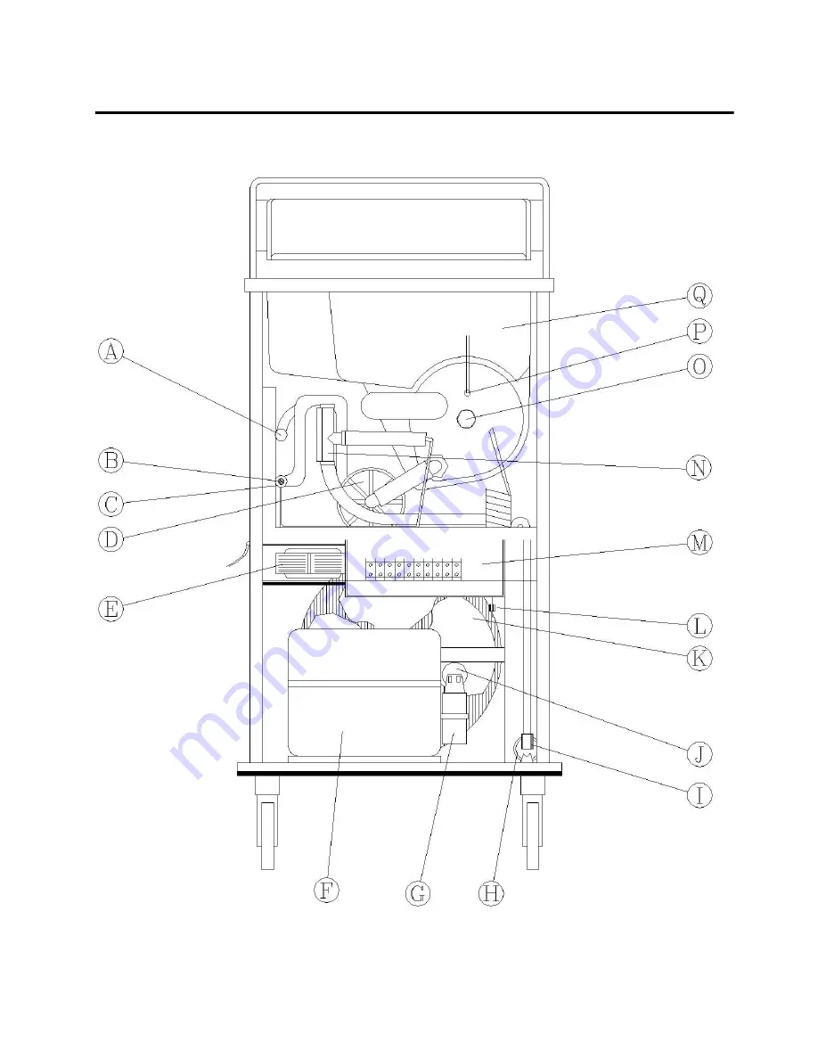
Page 67: ...perature sensor C Lower manifold outlet D Pump housing assembly E Transformer F Compressor G Compressor electrical box H Filter drier I Refrigeration solenoid valve J Starting capacitor K Condenser fa...
Page 68: ...FIELD REPAIR SERVICE BLANKETROL II Model 222S OPERATION AND TECHNICAL MANUAL Page 68 of 110 Figure 5 1 BLANKETROL II EXPOSED REAR VIEW...
Page 69: ...aps of the two screws on the left side and right side of the unit B Remove the four Phillips screws C Carefully lift up the front edge of the top of the unit so that you can see the stainless steel di...
Page 70: ...needed to detach the panel from the device D Set the left side enclosure panel to the side E Installation is reverse of removal 5 1 4 Disconnecting The Cables From The Microprocessor Board A Remove th...
Page 71: ...ve the 4 power supply wires by loosening the screws that tighten the wires in place F The top of the unit may now be removed from the base 5 1 5 Extending The Front Storage Drawer A Open the front sto...
Page 72: ...s H Re connect the wires from the heater to proper terminal I Replace the rear enclosure panel as described in Section 5 1 1 J Refill the reservoir as described in Section 4 2 5 5 3 REPLACEMENT OF THE...
Page 73: ...HOUSING A Obtain a replacement pump housing B Drain the reservoir as described in Section 4 2 4 C Remove the rear enclosure panel as described in Section 5 1 1 D Locate the white pump housing assembl...
Page 74: ...d in Section 4 3 O Refill the reservoir as described in Section 4 2 5 P Replace the rear enclosure panel as described in Section 5 1 1 5 5 REPLACEMENT OF THE PUMP MOTOR A Obtain a replacement pump mot...
Page 75: ...et connector that is disconnected by unscrewing the ground screw NOTE Do not disturb any of the other connections M Remove the pump motor from the unit Be sure to save the rubber gasket from beneath t...
Page 76: ...nt edge of the top of the unit so that you can see the wire harnesses and their termination points on the microprocessor board J Locate and disconnect the two 2 position flow switch connector J9 posit...
Page 77: ...ay be water in the line G Insert and tighten the replacement water temperature sensor into the lower water manifold Use Teflon tape on the sensor threads H Connect the water temperature sensor by inse...
Page 78: ...there may be water in the line F Using a 9 16 open end wrench unscrew and remove the three male quick disconnect fittings from the outside of the unit G Disconnect the by pass line from the reservoir...
Page 79: ...he unit U Reconnect the three female quick disconnect fittings on the top row starting with the fitting farthest from the water flow indicator Check that the fittings are screwed tight V Connect the h...
Page 80: ...ht side front view wall the connecting hose at its top left and the connecting hose at its top right E Disconnect the hose at the top left of the water flow indicator by loosening the screw clamp Be c...
Page 81: ...plastic elbow and tighten the clamp Q Refill the water reservoir as described in Section 4 2 5 R Reposition the front storage drawer as described in Section 5 1 6 5 12 REPLACEMENT OF THE I O POWER SW...
Page 82: ...5 in Figure 6 2 E Disconnect the water level sensor by pulling apart the white 2 pin connector J4 position F Using a 5 16 wrench remove the four nuts from the screw posts in the four corners of the wa...
Page 83: ...emove the six stand offs Remove the membrane control panel from the top assembly NOTE Be careful not to over tighten standoffs H Appropriately insert the replacement membrane control panel into the to...
Page 84: ...everse of removal 5 16 REPLACEMENT OF THE POWER CORD A Disconnect and remove each of the wires from the electrical box The white and black wires are terminated with slide off connector The green wire...
Page 85: ...ge Current tester and plug the tester into a power source B Attach the input lead wire of the tester to a grounding point of the BLANKETROL II unit 5 17 2 Taking Measurements In Normal Polarity A Set...
Page 86: ...ROL button The SETPOINT STATUS display must show COOLING D Set the BLANKETROL II unit so that it is HEATING and record the Leakage Current To set the unit in the heating cycle 5 Press the power switch...
Page 87: ...e power switch is defective or tripped Check amperage at switch a If the amp reading is less than 15 amperes the circuit breaker may be defective b If the amp reading is greater than 15 amperes check...
Page 88: ...has failed Replace microprocessor board See section 5 14 G Unit is on When the TEST INDICATOR is pressed the displays across the panel show an atypical pattern Microprocessor board malfunctions Repla...
Page 89: ...larm sounds Replace the probe jack Assembly I The probe from the patient is inserted but when operating in MANUAL CONTROL MODE the PATIENT display does not light up and alarm doesn t sound The patient...
Page 90: ...obe with a new 400 Series probe Cable from the probe jack to microprocessor board is disconnected Reconnect cable See Section 5 14 Probe jack on side of unit is defective Replace probe jack assembly L...
Page 91: ...on and off the unit goes to CHECK SETPT in the SETPOINT STATUS display or SENSOR FAULT REMOVE FROM SERVICE or HIGH LIMIT REMOVE FROM SERVICE Low line voltage or power source Check line voltage Reset...
Page 92: ...c Pump not working Check pump R Unit is operating in one of the control modes the SETPOINT STATUS display flashes LOW LIMIT REMOVE FROM SERVICE The back up low limit safety device is triggered which s...
Page 93: ...on 2 2 Kink in connecting hose and or blanket Straighten out the hose Clogged water filter Clean water filter See Section 4 2 Clogged tubing of blankets Use forced air to drain blankets Clogged coupli...
Page 94: ...t b If line voltage is not present Replace micro processor board See Section 5 14 V Unit is set to operate in a control mode Blanket does not heat Operator error switches not set correctly Water not c...
Page 95: ...part number as well as the serial number of your unit located on the identification plate on the rear bumper There is no minimum order requirement for replacement parts Section 6 2 outlines the recomm...
Page 96: ...indicates the quarter first 2 indicates that the unit is a BLANKETROL II Model 222S 60000 indicates that this is the 60 000th unit of a certain model D Date of installation or purchase E Return Mater...
Page 97: ...embly 115V White Reservoir Lid Assembly 230V 6 Strain Relief 7 Manifold Pan 8 1 8 Socket Quick disconnect Fitting Female 9 1 8 Plug Quick disconnect Fitting Male 10 12 ft Lead in Power Cord with Plug...
Page 98: ...FIELD REPAIR SERVICE BLANKETROL II Model 222S OPERATION AND TECHNICAL MANUAL Page 98 of 110 Figure 6 2 BLANKETROL II INTERNAL EXPLODED FRONT VIEW 12 10 11 9 6 7 14 13 15 1 2 3 5 4 8...
Page 99: ...asters Locking 4 Casters Non Locking 16 Drier 17 Solenoid Valve Body Solenoid Valve Coil 115V Solenoid Valve Coil 230V 18 Compressor 115V Compressor 230V 19 Terminal Block 20 Transformer Assembly 115V...
Page 100: ...FIELD REPAIR SERVICE BLANKETROL II Model 222S OPERATION AND TECHNICAL MANUAL Page 100 of 110 Figure 6 4 BLANKETROL II INTERNAL EXPLODED REAR VIEW...
Page 101: ...VICE BLANKETROL II Model 222S OPERATION AND TECHNICAL MANUAL Page 101 of 110 Figure 6 5 BLANKETROL II ELECTRICAL WIRING DIAGRAM 115V Note Beeper is located on the board for most devices built before 2...
Page 102: ...VICE BLANKETROL II Model 222S OPERATION AND TECHNICAL MANUAL Page 102 of 110 Figure 6 6 BLANKETROL II ELECTRICAL WIRING DIAGRAM 230 V Note Beeper is located on the board for most devices built before...
Page 103: ...FIELD REPAIR SERVICE BLANKETROL II Model 222S OPERATION AND TECHNICAL MANUAL Page 103 of 110 Figure 6 7 BLANKETROL II WATER CIRCULATION DIAGRAM...
Page 104: ...FIELD REPAIR SERVICE BLANKETROL II Model 222S OPERATION AND TECHNICAL MANUAL Page 104 of 110 Figure 6 8 BLANKETROL II REFRIGERATION FLOW DIAGRAM...
Page 105: ...Blanket Extension Hose with Couplings Head Wrap Single Patient Use Pad 600 Adult Head Wrap KOOL KIT Single Patient Use Convenience Kits 900 Kool Kit Adult Head Wrap Patient Vest and Lower Body Pad 910...
Page 106: ...FIELD REPAIR SERVICE BLANKETROL II Model 222S OPERATION AND TECHNICAL MANUAL Page 106 of 110 4872MS Therma Temp Connecting Cable Molex connection Figure 6 9 BLANKETROL II SYSTEM ACCESSORIES...
Page 107: ...trol Setting 4 0 C 39 2 F Low Limit Safety 2 0 C 2 0 C 35 6 F 3 6 F Low Limit Secondary Back up Safety 2 0 C 2 0 C 35 6 F 3 6 F Defective or Dislodged Probe Alarm Audible Visual Primary Secondary High...
Page 108: ...the Blanketrol II Model 222S unit is twelve 12 years from the date of manufacture provided the product is not subject to misuse negligence accident or abuse and under the conditions that the device is...
Page 109: ...Compliance level Electromagnetic environment guidance Electrostatic discharge ESD IEC 61000 4 2 6 kV contact 8 kV air 6 kV contact 8 kV air Floors should be wood concrete or ceramic tile If floors are...
Page 110: ...ecommended separation distance in meters m Field strengths from fixed RF transmitters as determined by an electromagnetic site survey a should be less than the compliance level in each frequency range...
Page 111: ...ording to frequency of transmitter m 150 kHz to 80 MHz d 1 2 P 80 MHz to 800 MHz d 1 2 P 800 MHz to 2 5 GHz d 2 3 P 0 01 0 12 0 12 0 23 0 1 0 38 0 38 0 73 1 1 2 1 2 2 3 10 3 8 3 8 7 3 100 12 12 23 For...
Page 112: ......
Page 113: ...Cincinnati Sub Zero Products LLC 12011 Mosteller Road Cincinnati OH 45241 Toll Free 1 800 989 7373 Fax 513 772 9119 www cszmedical com...