


September 2015
Service and Repair Manual
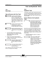
Fuel and Hydraulic Tanks
Part No. 1268515
Z-34/22 Bi-Energy
57
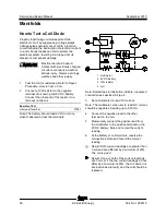
Fuel and Hydraulic Tanks
10- 1 F uel Tank
10-1
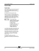
Fuel Tank
How to R emove the Fuel T ank
How to Remove the Fuel Tank
Explosion and fire hazard.
Engine fuels are combustible.
Perform this procedure in an
open, well-ventilated area away
from heaters, sparks, flames and
lighted tobacco. Always have an
approved fire extinguisher within
easy reach.
Explosion and fire hazard. When
transferring fuel, connect a
grounding wire between the
machine and pump or container.
Explosion and fire hazard. Never
drain or store fuel in an open
container due to the possibility of
fire.
1 Using an approved hand-operated pump,
drain the fuel tank into a suitable container.
Refer to Specifications,
Machine
Specifications
.
2 Remove the fuel tank retaining fastener
located underneath the tank mounting tray at
the bottom of the fuel tank.
Component damage hazard. The
fuel tank is plastic and may
become damaged if allowed to
fall.
Component damage hazard. Do
not overtighten the fuel tank
mounting fasteners.
Note: Clean the fuel tank and inspect for cracks
and other damage before installing.
10- 2 Hydraulic T ank
10-2
Hydraulic Tank
The primary functions of the hydraulic tank are to
cool, clean and deaereate the hydraulic fluid during
operation. It utilizes internal suction strainers for
the pump supply suction lines and has an external
return line filter.
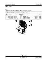
How to R emove the H ydr aulic Tank
How to Remove the Hydraulic
Tank
Component damage hazard. The
work area and surfaces where
this procedure will be performed
must be clean and free of debris
that could get into the hydraulic
system and cause severe
component damage. Dealer
service is recommended.
Note: When removing a hose assembly or fitting,
the O-ring (if equipped) on the fitting and/or hose
end must be replaced. All connections must be
torqued to specification during installation. Refer to
Specifications,
Hydraulic Hose and Fitting Torque
Specifications.
1 Close the hydraulic shutoff valve located at
the hydraulic tank.
Component damage hazard.
The machine must not be
operated with the hydraulic tank
shutoff valve in the closed
position or component damage
will occur. If the tank valve is
closed, remove the key from the
key switch and tag the machine
to inform personnel of the
condition.
Summary of Contents for Z-22 Bi-Energy
Page 63: ...September 2015 Service and Repair Manual Manifolds Part No 1268515 Z 34 22 Bi Energy 51...
Page 99: ...September 2015 Service and Repair Manual 87 Electrical Schematic from serial number 5427 CE...
Page 102: ...Service and Repair Manual September 2015 90 Electrical Schematic from serial number 5427 CE...
Page 103: ...September 2015 Service and Repair Manual 91 Ground Control Box Switch Panel Wiring Diagram...
Page 106: ...Service and Repair Manual September 2015 94 Ground Control Box Terminal Strip Wiring Diagram...
Page 107: ...September 2015 Service and Repair Manual 95 Platform Control Box Wiring Diagram...
Page 110: ...Service and Repair Manual September 2015 98 Power Cable Wiring Diagram...
Page 111: ...September 2015 Service and Repair Manual 99 Drive Contactor Panel Wiring Diagram...
Page 114: ...Service and Repair Manual September 2015 102 Manifold and Limit Switch Wiring Diagram...
Page 119: ...September 2015 Service and Repair Manual 107 Engine Wiring Diagram...
Page 123: ......


