


Service and Repair Manual
September 2015
Platform Components
18
Z-34/22 Bi-Energy
Part No. 1268515
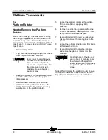
2-2 Platform Rotator
2-2
Platform Rotator
How to R emove the Pl atform Rotator
How to Remove the Platform
Rotator
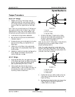
Note: When removing a hose assembly or fitting,
the O-ring (if equipped) on the fitting and/or hose
end must be replaced. All connections must be
torqued to specification during installation. Refer to
Specifications,
Hydraulic Hose and Fitting Torque
Specifications.
1 Remove the platform.
2 Tag, disconnect and plug the hydraulic hoses
from the platform rotate manifold.
Bodily injury hazard. Spraying
hydraulic oil can penetrate and
burn skin. Loosen hydraulic
connections very slowly to allow
the oil pressure to dissipate
gradually. Do not allow oil to
squirt or spray.
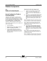
3 Support the platform mounting weldment with
a suitable lifting device. Do not apply any
lifting pressure.
4 Remove the six mounting bolts from the
platform mounting weldment. Remove the
center bolt and slide the platform mounting
weldment off of the platform rotator.
5 Support the platform rotator with a suitable
lifting device. Do not apply any lifting
pressure.
6 Remove the pin retaining fasteners from the
jib boom and leveling links to platform rotator
pivot pins. Do not remove the pins.
7 Use a soft metal drift to remove the leveling
link pivot pin. Lower the leveling links to the
ground.
8 Support the jib boom and jib boom lift cylinder
with an overhead crane.
9 Use a soft metal drift to drive both pins out
and remove the platform rotator from the
machine.
Crushing hazard. The jib boom
and jib boom lift cylinder could
fall when when the platform
rotator is removed if not properly
supported by the overhead
crane.
Note: When installing the platform rotator, be sure
to torque the fasteners to specification. Refer to
Specifications,
Machine Torque Specifications.
Summary of Contents for Z-22 Bi-Energy
Page 63: ...September 2015 Service and Repair Manual Manifolds Part No 1268515 Z 34 22 Bi Energy 51...
Page 99: ...September 2015 Service and Repair Manual 87 Electrical Schematic from serial number 5427 CE...
Page 102: ...Service and Repair Manual September 2015 90 Electrical Schematic from serial number 5427 CE...
Page 103: ...September 2015 Service and Repair Manual 91 Ground Control Box Switch Panel Wiring Diagram...
Page 106: ...Service and Repair Manual September 2015 94 Ground Control Box Terminal Strip Wiring Diagram...
Page 107: ...September 2015 Service and Repair Manual 95 Platform Control Box Wiring Diagram...
Page 110: ...Service and Repair Manual September 2015 98 Power Cable Wiring Diagram...
Page 111: ...September 2015 Service and Repair Manual 99 Drive Contactor Panel Wiring Diagram...
Page 114: ...Service and Repair Manual September 2015 102 Manifold and Limit Switch Wiring Diagram...
Page 119: ...September 2015 Service and Repair Manual 107 Engine Wiring Diagram...
Page 123: ......


