

• Use caution when working with voltages above
42VAC
RMS
, or 60VDC. These voltages pose a shock hazard.
• Use the proper terminals, function and range for all measurements.
•
•
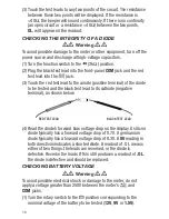
WARNING
Do not operate the meter around explosive gas, vapor,
or dust.
•
•
WARNING
When using the probes, keep your fingers behind the
finger guards. Do not touch the metal probes of the test leads when
making a measurement.
• When making connections, connect the black (–) test lead before
connecting the red (+) test lead; when disconnecting, disconnect the
red (+) test lead before disconnecting the black (–) test lead.
• Disconnect circuit power and discharge all high-voltage capacitors
before measuring/testing resistance, continuity, diodes, or
capacitance.
• For all DC functions in both auto and manual ranging mode, to avoid
the risk of shock due to possible improper reading verify the
presence of any AC voltages by first using the AC function. Then
select a DC voltage range equal to or greater than the AC range.
• Before measuring current, turn off power to the circuit before
connecting the meter.
• Do not operate the meter with the case (or part of the case)
removed.
• Use only (1) “9V” battery, properly installed in the battery
compartment, to power the meter. Do not use rechargeable
batteries.
• Replace the battery as soon as the low battery indicator “
”
appears. Operated with a weak battery, the meter might produce
false readings that could lead to electric shock and personal injury.
• Remove the test leads from the meter before opening the meter
case or battery compartment.
5


