4 - 26
Maintenance and Repair
DISASSEMBLY/ASSEMBLY INSTRUCTIONS
ACTUATOR SUBASSEMBLY
1.
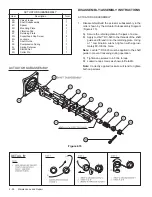
Disassemble/Build the actuator subassembly in the
order shown by the Actuator Subassembly Diagram
(Figure 4.15).
A) Secure the retaining plate in the jaws of a vise.
B) Apply Loctite™ RC-620 to the threads of the shaft
guide and thread it into the retaining plate. Using
a 1" combination wrench tighten with approxi-
mately 80-100 lbs. force.
Note: Loctite™ RC-620 must be applied to the shaft
guide to prevent loosening during operation.
C) Tighten cap screws to 4-5 lbs. torque.
D) Lockwire cap screws as shown in Detail B.
Note: Correctly applied lockwire will tend to tighten
both cap screws.
ACTUATOR SUBASSEMBLY
Item
Description
Total
2A
Valve Flange
1
2B
Shaft Subassembly
1
2C
Spacer
4
2D
Mounting Plate
1
2E
Vibration Pad
1
2F
Retaining Plate
1
2G
Sockethead Cap Screw
4
2H
Lockwire
1
2J
Shaft Guide
1
2K
Compression Spring
1
2L
Spring Retainer
1
2M
Slotted Nut
1
2N
Cotter Pin
1
ACTUATOR SUBASSEMBLY
DETAIL 'B'
Figure 4.15


