


Operation
3 - 1
3
Operation
through test and analysis when a specific quality pro-
cess gas is required.
4.
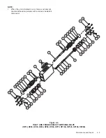
Refer to the applicable drawings which accompany
this manual as necessary for component identification
and location while conducting start-up and operational
procedures.
Note: If your dryer cannot be started, or fails to start
due to special installation or other problems, contact
your local General Pneumatics Sales Representative
for assistance.
5.
Close the customer-supplied System Inlet Isolation
Valve.
6.
Open customer-supplied System Bypass Valve, if in-
stalled.
7.
Close customer-supplied System Outlet Isolation
Valve.
8.
Supply compressed air up to Inlet Isolation Valve.
9.
Open Pilot Gas Supply Valve, located upstream of
the Pilot Gas Filter.
10. Supply pressure to system by SLOWLY opening Sys-
tem Inlet Isolation Valve (customer-supplied). Both
desiccant chamber Inlet Switching Valves will open
and both chamber Purge Exhaust Valves will close.
The desiccant chambers will immediately begin pres-
surizing to system pressure as indicated by chamber
pressure gauges.
11. The Moisture Indicator's (if dryer so-equipped) bleed
valve is installed directly into the back of the
indicator's body. Close the Indicator's Bleed Valve.
FULLY open the Moisture Indicator Supply Valve.
12. Soap bubble test all external piping, fittings, and con-
nections. Locate and repair all noted points of leak-
age. Do not soap bubble test components lo-
cated inside dryer control system's enclosure.
Note: Small leaks noted in inlet piping to the dryer
will not affect operation, other than a slight loss of
pressure supplied to the dryer. HOWEVER, any gas
3.1
Start-Up
WARNING!
Ensure that the dryer is de-energized, valve isolated
and fully depressurized before attempting to remove
or disassemble any dryer component or subassembly.
Failure to do so may result in serious personal injury
and/or equipment damage.
CAUTION: Each component of a General Pneumatics
Regenerative Desiccant Dryer System has been selected
to compliment the performance of the other components of
the system. Therefore, use of unauthorized parts or sup-
plies or improper operation will degrade system perfor-
mance.
Note: All filter assemblies are shipped WITH filter car-
tridges installed. Prefilter and Afterfilter Cartridges are
NOT interchangeable and must be installed in their respec-
tive assemblies ONLY. The proper filter cartridge part
number is listed on each prefilter and afterfilter assembly.
Dryer Models OP15 through OP200
1.
Close any manual vent or drain valves installed in
prefilter and afterfilter assemblies.
2.
If the prefilter assembly was factory equipped with an
automatic drain valve or drain trap, inspect for, and
remove pipe plug or cap which may have been in-
stalled in drain port for shipping purposes.
3.
Ensure that all associated pipe and tubing connec-
tions, flanges, unions, plugs, mounting bolts, pipe
hangers, etc., have been checked tight and/or prop-
erly secured.
IMPORTANT: It is recommended that the System's
process gas output not be consumed or used at the
intended points of use until the Start-Up and any re-
lated adjustments have been completed, and the sys-
tem is producing process gas of the required quality.
The quality of the process gas should be verified