Maintenance and Repair
4 - 27
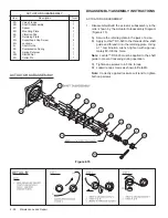
SHAFT SUBASSEMBLY
Item
Description
Total
2B1
Poppet Shaft
1
2B2
Orifice Plate
1
2B3
Orifice Spring
1
2B4
Washer
1
2B5
Slotted Nut
1
2B6
Cotter Pin
1
SHAFT SUBASSEMBLY
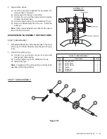
DETAIL 'C'
2.
Adjust orifice stroke.
A) Invert the actuator subassembly and place in a
vice as shown in Detail C.
B) Gently press the flange to the orifice.
C) Tighten the nut until the spring retainer slightly
contacts the shaft guide.
D) Continue tightening nut for an additional 1/2 turn.
E) Remove subassembly from the vice. Install the
cotter pin.
Note: Orifice stroke adjustment is critical to the opera-
tion of the flow restrictor.
DISASSEMBLY/ASSEMBLY INSTRUCTIONS
SHAFT SUBASSEMBLY
1.
Disassemble/Build the shaft subassembly in the order
shown by the Shaft Subassembly Diagram (Figure
4.16).
2.
Preload the orifice spring.
A) Tighten nut until slight contact is made with
washer and orifice spring.
B) Continue tightening nut an additional 3 turns.
C) Install cotter pin.
Note: Preloading of the orifice spring is critical to the
operation of the flow restrictor.
Figure 4.16


