Operation
24
MLT6SM/K-8SK Operating Manual
17973 G
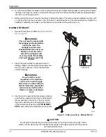
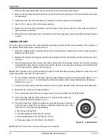
1. Remove the power cables from the two terminals on the winch motor assembly (A).
2. Remove the two flange head screws (B) securing the winch motor assembly to the winch. Retain the screws
for reassembly.
3. Carefully remove the motor assembly (C), making sure the two pieces do not separate.
4. Insert a 3/8 in. hex key (D) into the sleeve bearing.
5. Rotate the wrench counter-clockwise to lower the mast. If any slack is observed in the cable, stop immedi-
ately and remove the slack.
6. When the mast is completely down, reinstall the winch motor assembly, securing it with the screws retained
in step 2.
TOWING THE UNIT
Once the engine is shut down, the mast and lights are properly stowed, and the unit is lowered so the weight is on
the wheels, follow these steps to prepare the unit.
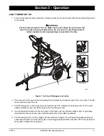
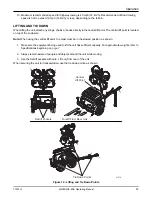
1. Raise the outrigger jacks completely and remove the locking pins to rotate them up into the travel position.
Replace the locking pins.
2. Release the outrigger locking pins and slide the outriggers into the trailer frame until the locking pins snap
into place.
3. Use the tongue jack to raise or lower the trailer onto the hitch of the towing vehicle. Lock the hitch coupling
and attach the safety chains or cables to the vehicle. Remove the tongue jack locking pin and rotate the jack
into the travel position. Replace the locking pin.
Note: A film of grease on the coupler will extend coupler life and eliminate squeaking. Wipe the coupler clean and
apply fresh grease each time the unit is towed.
4. To ensure proper operation of the jacks, lube the grease fittings located on the leveling jacks. Refer to
“Jack
Maintenance” on page 31.
For maintenance interval information, refer to Basic Maintenance Schedules
beginning on
page 28.
5. Connect any trailer wiring to the tow vehicle. Check for proper operation of the directional and brake lights.
6. Make sure the enclosure is properly latched.
7. If the unit is going to be driven over rough ground, remove the bulbs from the light fixtures.
8. Check for proper inflation of the trailer tires. For maximum tire pressures,
refer to Specifications
beginning
on
page 7
.
9. Check the wheel lugs. Tighten or replace any lugs that are loose or missing. If
a tire has been removed for axle service or replaced, tighten the lugs, in the
order shown, to the following specifications:
a. Start all lug nuts by hand.
b. First pass tighten to 20-25 ft-lbs (27-33 Nm).
c. Second pass tighten to 50-60 ft-lbs (67-81 Nm).
d. Third pass tighten to 90-120 ft-lbs (122-162 Nm).
Figure 15 - Lug Sequence
Note: After the first road use, re-torque the lug nuts in sequence.
1
2
3
4
5
6
00205
Summary of Contents for MLT6SK
Page 4: ...iv This Page Intentionally Left Blank ...
Page 12: ...Safety 6 MLT6SM K 8SK Operating Manual 17973 G This Page Intentionally Left Blank ...
Page 32: ...Operation 26 MLT6SM K 8SK Operating Manual 17973 G This Page Intentionally Left Blank ...
Page 34: ...Maintenance 32 MLT6SM K 8SK Operating Manual 17973 G This Page Intentionally Left Blank ...
Page 36: ......

