background image

Safety

17973 G

MLT6SM/K-8SK Operating Manual

3

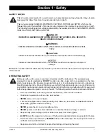
SERVICE SAFETY

All service work must be performed by qualified personnel who are familiar with the equipment. Only a 
qualified electrician should troubleshoot or repair electrical problems occurring in this equipment. Fol-
low the safety guidelines described below to prevent hazardous situations which could result in severe 
injury or death.

NEVER

 wash the unit with high pressure hoses, power washers, or steam cleaners. Water may collect 

in the unit, causing damage to electrical parts.

ALWAYS 

use extreme caution when servicing this unit in damp conditions. Do not service the unit if 

your skin or clothing is wet. Do not allow water to collect around the base of the unit.

Replace all missing and hard to read decals. Decals provide important operating instructions and 
warn of dangers and hazards.

Before servicing the unit, make sure the Key switch and circuit breakers are in the OFF (O) position, 
and the negative (-) terminal on the battery is disconnected. 

NEVER

 perform even routine service 

(oil/filter changes, cleaning, etc.) unless all electrical components are shut down.

NEVER

 start the unit under load. The circuit breakers must be in the OFF (O) position when starting 

the unit.

Wear heavy leather gloves when handling winch cables. Never let cables slip through bare hands.

TOWING SAFETY

Towing a trailer requires care. Both the trailer and vehicle must be in good condition and securely fastened 
to each other to reduce the possibility of an accident. Some states require that large trailers be registered 
and licensed. Contact your local Department of Transportation office to check on license requirements for 
your particular unit. 

Check that the hitch and coupling on the towing vehicle are rated equal to, or greater than, the trailer's 
Gross Vehicle Weight Rating (GVWR). 

Check tires on trailer for tread wear, inflation, and condition.

NEVER

 tow trailer using defective parts. Inspect the hitch and coupling for wear or damage. 

Make sure the trailer hitch and the coupling are compatible. Make sure the coupling is securely fastened 
to the vehicle.

Make sure directional and brake lights on the trailer are connected and working properly.

Check that the lug nuts holding the wheels are tight and that none are missing.

Maximum recommended speed for highway towing is 45 mph (72 km/h). Recommended off-road 
towing speed is not to exceed 10 mph (16 km/h) or less, depending on terrain.

When towing, maintain extra space between vehicles and avoid soft shoulders, curbs and sudden 
lane changes. If you have not pulled a trailer before, practice turning, stopping and backing up in an 
area away from heavy traffic. 

A film of grease on the coupler will extend coupler life and eliminate squeaking. Wipe the coupler 

clean and apply fresh grease each time the trailer is towed.

Connect safety chains in a crossing pattern under the tongue.

Before towing the trailer, check that the weight of the trailer is equal across all tires. On trailers with 
adjustable height hitches, adjust the angle of the trailer tongue to keep the trailer as level as possible. 

REPORTING TRAILER SAFETY DEFECTS

If you believe your trailer has a defect which could cause a crash or could cause injury or death, you should immediately 
inform the National Highway Traffic Safety Administration (NHTSA) in addition to notifying Generac Mobile Products 

Summary of Contents for MLT6SK

Page 1: ...OPERATING MANUAL Parts manuals available online at www generacmobile com 17973 G 07 15 00749 LIGHT TOWER MLT6SM MLT6SK MLT8SK ...

Page 2: ...s constituents are known to the state of California to cause cancer birth defects and other reproductive harm WARNING CALIFORNIA PROPOSITION 65 WARNING This product contains or emits chemicals known to the state of California to cause cancer birth defects and other reproductive harm ...

Page 3: ...r which it was designed Generac Mobile Products recommends that a trained and licensed professional perform all electrical wiring and testing functions Any wiring should be in compliance with the National Electrical Code NEC state and local regulations and Occupational Safety and Health Administration OSHA guidelines GENERAC MOBILE PRODUCTS LLC 215 Power Drive Berlin WI 54923 U S A Phone 920 361 4...

Page 4: ...iv This Page Intentionally Left Blank ...

Page 5: ...utdown 22 Lowering the Mast Manual 23 Lowering the Mast Electric Winch Option 23 Electronically Lowering the Mast 23 Manually Lowering the Mast 23 Towing the Unit 24 Lifting and Tie Down 25 Section 4 Maintenance Daily Walk Around Inspection 27 General Maintenance 27 Basic Maintenance Schedule Mitsubishi Engine 28 Basic Maintenance Schedule Kubota Engine 29 Winch Use Operation and Maintenance Manua...

Page 6: ...K 37 DC Wiring Mitsubishi 38 DC Wiring Kubota 39 DC Wiring Electric Winch 40 DC Wiring Option Heated Fuel Filter Mitsubishi 41 DC Wiring Option Heated Fuel Filter Kubota 42 Trailer Lights Wiring 43 Section 7 Options Accessories Lower Radiator Hose Heater Option Use and Maintenance 45 Service Log 47 ...

Page 7: ...f the instructions This equipment was designed for specific applications DO NOT modify or use this equipment for any application other than which it was designed for Equipment operated improperly or by untrained personnel can be dangerous Read the operating instructions and familiarize yourself with the location and proper use of all instruments andcontrols Inexperiencedoperatorsshouldreceiveinstr...

Page 8: ...n and fueling Failure to follow the safety guidelines described below could result in severe injury or death Read and follow all safety warnings described in the engine operator s manual A copy of this manual was supplied with the unit when it was shipped from the factory DO NOT run engine indoors or in an area with poor ventilation unless exhaust hoses are used Engine exhaust contains carbon mono...

Page 9: ... licensed Contact your local Department of Transportation office to check on license requirements for your particular unit Check that the hitch and coupling on the towing vehicle are rated equal to or greater than the trailer s Gross Vehicle Weight Rating GVWR Check tires on trailer for tread wear inflation and condition NEVER tow trailer using defective parts Inspect the hitch and coupling for we...

Page 10: ...n However NHTSA cannot become involved in an individual problem between you your dealer or Generac Mobile Products LLC To contact NHTSA you may either call the Auto Safety Hotline toll free at 1 888 327 4236 TTY 1 800 424 9153 go to http www safercar gov or write to Administrator NHTSA 1200 New Jersey Avenue S E Washington DC 20590 You can also obtain other information about motor vehicle safety f...

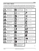
Page 11: ... Run engine Engine start Wind hazard do not set up in wind speeds greater than 60 mph 95 km h Dangerous voltage may be present Asphyxiation hazard operate in well venti lated area Fan hazard keep body parts clear of this area Belt entanglement hazard keep body parts clear of this area Safety alert symbol used to alert you to potential hazards Do not operate unit indoors or in an area with poor ven...

Page 12: ...Safety 6 MLT6SM K 8SK Operating Manual 17973 G This Page Intentionally Left Blank ...

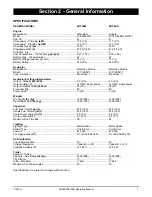
Page 13: ... 6 0 6 0 Output Voltage V 120 240 single phase 120 240 single phase Output Amperes 120V 240V A 50 25 50 25 Frequency Hz 60 60 Power Factor 1 1Ø 1 1Ø Weights Dry Weight lbs kg 1290 585 1330 603 Operating Weight lbs kg 1560 708 1600 726 Capacities Fuel Tank Volume gal L 43 5 165 43 5 165 Usable Fuel Volume gal L 43 5 165 43 5 165 Coolant incl engine qt L 4 5 4 3 4 8 4 5 Oil incl filter qt L 5 0 4 7 ...

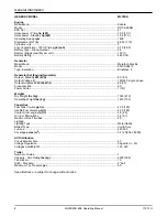
Page 14: ...kW kVA 8 0 8 0 Output Voltage V 120 240 single phase Output Amperes 120V 240V A 66 33 Frequency Hz 60 Power Factor 1 1Ø Weights Dry Weight lbs kg 1349 612 Operating Weight lbs kg 1619 734 Capacities Fuel Tank Volume gal L 43 5 165 Usable Fuel Volume gal L 43 5 165 Coolant incl engine qt L 4 8 4 5 Oil incl filter qt L 5 4 5 1 Maximum Run Time hrs 60 Lighting Lighting Type Metal Halide Ballast Type ...

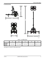
Page 15: ...LT6SM K 8SK Operating Manual 9 Unit Dimensions Figure 1 Unit Dimensions Specifications are subject to change without notice A B C D E MLT6SM MLT6SK MLT8SK 118 in 3 m 101 in 2 6m 23 ft 7 m 57 in 1 45 m 120 5 in 3 1 m 00751 D E C A B ...

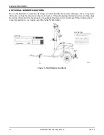
Page 16: ...Form SFC626B Manufactured by Generac Mobile Products LLC 920 361 4442 800 926 9768 TIRE AND LOADING INFORMATION RENSEIGNEMENTS SUR LES PNEUS ET LE CHARGEMENT SEE OWNER S MANUAL FOR ADDITIONAL INFORMATION VOIR LE MANUEL DE L USAGER POUR PLUS DE RENSEIGNEMENTS MANUFACTURED BY FABRIQUE PAR Generac Mobile Products LLC DATE 00 0000 GVWR PNBV 000KG 0000LBS COLD INF PRESS PRESS DE V I N N I V 00000000000...

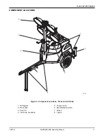
Page 17: ...T6SM K 8SK Operating Manual 11 COMPONENT LOCATIONS Figure 3 Component Locations Front and Left Side 1 Outriggers 5 Tongue Jack 2 Rear Jack 6 Mast Rotation Knob 3 Fuel Fill 7 Winch 4 Tie Down Locations 8 Lights 6 3 1 8 5 2 7 4 01742 ...

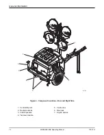
Page 18: ...LT6SM K 8SK Operating Manual 17973 G Figure 4 Component Locations Rear and Right Side 1 Central lift point 5 Control box 2 Radiator access 6 Rear jack 3 Forklift pockets 7 Engine access 4 Tie down location 5 1 3 7 2 6 4 01743 ...

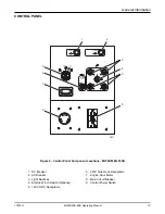
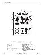
Page 19: ...MLT6SK 1 DC Breaker 6 240V Twist Lock Receptacle 2 AC Breaker 7 Engine Hour Meter 3 Light Switches 8 Main Circuit Breaker 4 Electric Winch Switch Optional 9 Control Power Switch 5 120V GFCI Receptacle 00757 I O I O I O I O MAIN BREAKER 240V I O STOP 15 SEC MAX 12V DC CIRCUIT BREAKER AC CIRCUIT BREAKER 120V 1 2 7 6 8 9 5 4 3 3 ...

Page 20: ...eakers 7 Engine Hour Meter 3 Light Switches 8 Main Circuit Breaker For Lights and GFCI Receptacles 4 Electric Winch Switch Optional 9 Control Power Switch 5 120V GFCI Receptacle 10 Main Circuit Breaker for Twist Lock Receptacle 00758 I O I O I O I O MAIN BREAKER 240V I O STOP 15 SEC MAX I O 12V DC CIRCUIT BREAKER AC CIRCUIT BREAKERS 120V 1 2 7 6 8 9 4 3 3 5 10 ...

Page 21: ...e on or near the unit dry if needed For grounding requirements follow any local state or National Electrical Code NEC guidelines Switch the Control Power switch to the OFF O position Switch all circuit breakers to the OFF O position Inspect all electrical cords repair or replace any that are cut worn or bare Ensure all winch cables are in good condition and centered on each pulley Do not use if ca...

Page 22: ...General Information 16 MLT6SM K 8SK Operating Manual 17973 G This Page Intentionally Left Blank ...

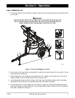
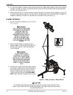
Page 23: ... the wheels to keep it from moving A This will make it easier to level the unit 3 Pull the locking pin on the tongue jack and rotate the jack 90 Replace the locking pin B Turn the jack handle clockwise to raise the trailer tongue off of the towing vehicle 4 A grounding stud is located on the rear frame of the trailer near the left side outrigger B For grounding requirements follow and local state ...

Page 24: ...evel the unit or extend the outriggers will severely reduce the stability and could allow the unit to tip and fall 2 Check the mast cables for excessive wear or damage Make sure the cables are properly cen tered in each pulley A Check the electrical cord for damage WARNING Do not start the unit if insulation on the electrical cord is cut or worn through Bare wires in contact with the mastorframema...

Page 25: ...e Make sure the cables are properly cen tered in each pulley A Check the electrical cord for damage WARNING Do not start the unit if insulation on the electrical cord is cut or worn through Bare wires in contact with the mastorframemayenergizethe unit and cause electrocution Repair or replace a damaged cord 3 Press and hold the winch control switch B upward to telescope the mast to the desired hei...

Page 26: ...riate glow plug interval Figure 11 Key Locations to Starting the Unit Do not crank the engine longer than 10 seconds at a time If the engine will not start wait 30 seconds to allow the starter motor to cool and then repeat the starting procedure Excessive cranking will cause damage to the starter Note If oil pressure is not obtained within 15 seconds after the key is switched to the Run position t...

Page 27: ...ass Any residue can create a hot spot on the bulb causing premature bulb failure CAUTION Bulbs become extremely hot when in use Allow bulb fixture to cool 10 15 minutes before handling or lowering the mast DERATING FOR ALTITUDE All units are subject to derating for altitude and temperature this will reduce the available power for operating tools and accessories connected to the receptacles Typical...

Page 28: ...t create any hazards by accidentally turning off equipment that needs to be kept on pumps compressors lights etc When you have finished using the unit proceed with shut down as follows 1 Remove any loads from the receptacles 2 Switch the individual circuit breakers for each light and each receptacle to the OFF O position 3 Switch the main circuit breaker to the OFF O position 4 Turn the Control Po...

Page 29: ... 2 If the unit is going to be moved it is recommended that the mast is turned so the lights face the rear of the unit To rotate the mast a Loosen the mast rotation knob b Rotate the mast until the white arrows are aligned and the metal stop tabs are touching c Tighten the mast rotation knob 3 Press and hold the upper winch control switch downward to collapse the mast to its lowest position Ensure ...

Page 30: ...tach the safety chains or cables to the vehicle Remove the tongue jack locking pin and rotate the jack into the travel position Replace the locking pin Note A film of grease on the coupler will extend coupler life and eliminate squeaking Wipe the coupler clean and apply fresh grease each time the unit is towed 4 To ensure proper operation of the jacks lube the grease fittings located on the leveli...

Page 31: ...nclosure Note When using the central lift point the mast must be in the stowed position as shown 1 Make sure the equipment being used to lift the unit has sufficient capacity For approximate weights refer to Specifications beginning on page 7 2 Always remain aware of people and objects around the unit while moving 3 Use the forklift pockets with care Lift only from rear of the unit When securing t...

Page 32: ...Operation 26 MLT6SM K 8SK Operating Manual 17973 G This Page Intentionally Left Blank ...

Page 33: ...g the unit always follow the instructions listed below Verify the Control Power switch is turned to the OFF O position Verify the circuit breakers are turned to the OFF O position Disconnect the negative terminal on the battery Attach a Do Not Start sign to the control panel This will notify everyone that the unit is being serviced and will reduce the chance of someone inadvertently trying to star...

Page 34: ...Maintenance 32 MLT6SM K 8SK Operating Manual 17973 G This Page Intentionally Left Blank ...

Page 35: ...AC On quick discon nect models measure across the junction box terminals when the light is unplugged On hard wired models remove the mast junction box cover and insert the wire probes into the connector blocks for the light and ground If proper voltage is not achieved perform capacitor check to determine if the capacitor or coil needs to be replaced Mast Lights On But the Light Output is Low 1 Fix...

Page 36: ......
Reviews: