


page | 28
B
asic Oper
ation
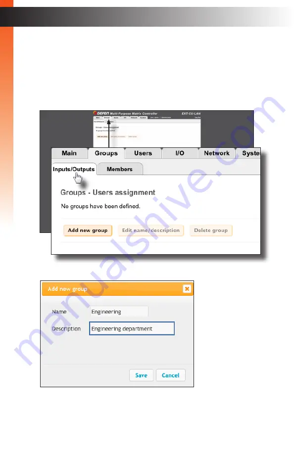
A
group
contains both a set of units (inputs and outputs) for routing and one or more users.
Once a group is created, we can add the units and the users that will be able to access
them. An unlimited number of groups can be created. See
for more information on groups.
1. Click the
Groups
tab.
2. Under the
Input/Output
tab, click the
Add new group
button.
3. The
Add new group
dialog box will be displayed.
4. Enter the name of the group in the
Name
field. Enter the description for the group
name in the
Description
field.
Creating Groups
B
asic Oper
ation
Summary of Contents for EXT-CU-LAN
Page 1: ...Audio Embedder 3GSDI EXT CU LAN User Manual Matrix Controller Release A1 1 Preferred...
Page 10: ......
Page 11: ...Matrix Controller 1 Getting Started...
Page 32: ......
Page 33: ...page 23 Matrix Controller 2 Basic Operation...
Page 114: ......
Page 115: ...Matrix Controller 3 Advanced Operation...
Page 157: ......
Page 158: ......
Page 159: ...page 149 Matrix Controller 4 Appendix...
Page 167: ......


