10.4.6 Removing the Adapter Module
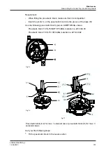
Fig.72
Carry out the following steps:
1.
Remove all cables from the connection terminals on the adapter module (47).
2.
Unscrew and remove the screws (57.2).
3.
Slacken the screws K (11-16 + 19-20) on the connection terminals of the
interface module (43) and pull the adapter module (47) out of the interface
module (43) by approx. 7 mm in the direction of the arrow and then remove it
from the base (5).
®
Done
Hint!
Assemble the adapter module in the reverse order. Pay attention to the
connection diagrams, see chapter “Connection diagram T.VIS M-15
with adapter module”
10.4.7 Removing the Interface Module
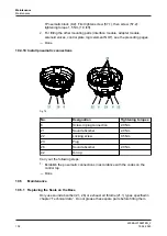
Fig.73
Carry out the following steps:
Maintenance
Dismantling the Control Top into its Components
430BAL010697EN_2
15.04.2020
99
Summary of Contents for T.VIS M-15
Page 6: ...430BAL010697EN_2 6 15 04 2020...
Page 53: ...Fig 27 Assembly and installation Electrical connections 430BAL010697EN_2 15 04 2020 53...
Page 55: ...Fig 28 Assembly and installation Electrical connections 430BAL010697EN_2 15 04 2020 55...
Page 119: ...Appendix 430BAL010697EN_2 15 04 2020 119...
Page 120: ......


