7.10.6
Oil injection
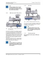
The injection oil is fed without a pump via the oil
injection regulating valve.
The oil injection control valve is used to adjust the
necessary compression discharge temperature.
The control valve is provided with a check function to
prevent sucking refrigerant through the oil pump.
7.10.7
Oil circuit, OMC block
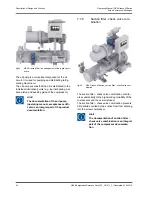
An OMC-block (oil management block) is flanged on
to the oil filter as an oil distributor system. The oil
flow is distributed via the bore-holes and channels to
functional ranges of the screw compressor. All regu-
lating valves and shut-off valves necessary for the
regulation of the oil circuit are integrated into the
block. As a result, a centralised control unit is availa-
ble for the screw compressor package.
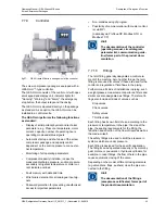
The oil filter with OMC-block (oil management block)
is fitted with an oil drain and refilling stop valve which
may be connected to a separate oil pump or
receiver.
Vent valves are fitted to oil filters for maintenance
and repair purposes.
The oil in oil filter may be drained for changing oil fil-
ter via a separate stop valve.
7.11
Capacity control
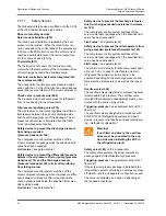
The screw compressors are fitted with a continuous
capacity control with a range of 10 -100%.
The capacity is adjusted by shortening the screw
compressor stroke. The defining factor for the com-
pression process is the effective rotor length; this is
altered by a hydraulically operated control slide.
The position of the control slide is recorded by the
position sensor. Upon reaching the MIN or MAX end
position, it is signalled to the control device and the
relative control slide position can be displayed in per-
centage on the touch panel.
The hydraulic adjustment of the control slide is real-
ised using solenoid valves, which are integrated into
a single block.
The control slide travel speeds in the MIN and MAX
directions should, to the extent possible, be the
same during operation to ensure better compressor
control.
7.12
Technical specifications
7.12.1
Designed for use in explosive
atmospheres!
Danger!
When operating the screw compressor
package in explosive atmospheres, the
special safety instructions for use in
explosive atmospheres that are men-
tioned in this operating manual must
be heeded.
Hint!
The screw compressor packages can
basically be used in explosive atmos-
pheres.
Some specifics must be heeded when using the
screw compressor packages in explosive atmos-
pheres of installation zones 1 and 2.
The basis for use in explosive atmospheres is the
following data of the operator:
–
Zone division as per EN 60079-10 (or other
equivalent international standards),
–
description of the atmosphere (required gas
groups),
–
required temperature class.
This data is stored in the request sheet for project
055 100A
. The
055 100A
request sheet is part of the
product documentation.
For using and placing a screw compressor package
into operation within the EU, the package is manu-
factured ATEX-compliant (see component selection,
protection systems, regulations, etc.)
The following marginal parameters generally apply:
–
The screw compressor packages can be instal-
led in Zones 1 and 2 in accordance with EN
60079-10.
–
The max. achievable temperature class is T4.
–
The screw compressor packages are not suita-
ble for carrying explosive mixtures; the suction
pressure of the package is always in the over-
pressure range.
Operating Manual | GEA Grasso M-Series
Screw Compressor Packages
Description of Design and Function
GEA Refrigeration Germany GmbH | P_261511_1 | Generated 01.04.2015
47
Summary of Contents for Grasso M-Series
Page 88: ......

