background image

This manual contains installation, operation, and maintenance 

instructions. Read thoroughly before beginning installation. Failure 

to follow these instructions may result in personal injury or death, 

damage to the unit, or incorrect operation.

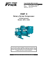
RWF II


Rotary Screw Compressor

All Refrigerants

Models 100 to 1080

Form 070.610-IOM (JUL 2021)

 Installation–Operation–Maintenance

File: 

Service Manual – Section 070

Replaces: 

070.610-IOM (MAR 2020)

Distribution:  3, 3a, 3b, 3c

Check www.FrickCold.com for the latest version of this publication.

Summary of Contents for RWF II 100

Page 1: ...y result in personal injury or death damage to the unit or incorrect operation RWF II Rotary Screw Compressor All Refrigerants Models 100 to 1080 Form 070 610 IOM JUL 2021 Installation Operation Maintenance File Service Manual Section 070 Replaces 070 610 IOM MAR 2020 Distribution 3 3a 3b 3c Check www FrickCold com for the latest version of this publication ...

Page 2: ...e power assist kit 31 Balance piston pressure regulator 31 Initial start up 31 Initial start up procedure 31 VFD skip frequencies 32 Normal start up procedure 32 Maintenance General information 33 Normal maintenance operations 33 General maintenance 33 Compressor shutdown and start up 33 General instructions for replacing compressor unit components 33 Oil filter OF 1 cartridge style 34 Strainer de...

Page 3: ... 10 F above the refriger ant saturation temperature This ensures that all refrigerant at the compressor suction is in the vapor state Design limitations The compressor units are designed for operation within the pressure and temperature limits as shown in Frick publication 070 610 SED Job inspection Immediately upon delivery examine all crates boxes and exposed compressor and com ponent surfaces f...

Page 4: ...Waynesboro 1153 Monterrey Month A JAN B FEB C MAR D APR E MAY F JUN G JUL H AUG K SEP L OCT M NOV N DEC Additional Remarks R Remanufactured R1 Rebuild R2 Rebuild Plus Z Deviation from standard configuration RWF II model Compressor model Rotor diameter Rotor Max speed Geo swept volume drive shaft end Displacement 4150 rpm 3550 rpm 2950 rpm mm L d rpm ft rev m rev cfm m h cfm m h cfm m h 100 SGC 191...

Page 5: ...a wood skid it must be removed before installing the unit WARNING Allow space for servicing the unit per factory draw ings The first requirement of the compressor foundation is that it must be able to support the weight of the compres sor package including coolers oil and refrigerant charge Screw compressors are capable of converting large quan tities of shaft power into gas compression in a relat...

Page 6: ... result Bump the motor to check for correct compressor rotation After verifica tion install disc drive spacer metal center section or elastomeric gear as applicable Compressor motor coupling installation The RWF II unit has compressor to motor alignment through the use of a machined cast iron tunnel This tun nel is factory set through machining tolerances ensuring motor compressor alignment No ali...

Page 7: ...ightening the clamp screws Torque is transmitted from the motor through the elastomeric gear which floats freely between the hubs Because of the use of the motor compres sor adapter housing on the RWF II no field alignment is necessary 1 Inspect the shaft of the motor and compressor to en sure that no nicks grease or foreign matter is present 2 Inspect the bores in the coupling hubs to make sure t...

Page 8: ...he compressor check for any oil migration Oil transfer may be needed Table 5 Model charge RWF II models Basic charge gal 100 119 SS 134 159 SS 45 or 50 177 209 SS 222 264 SS 90 270 316 375 SS 399 472 SS 120 480 546 130 496 190 676 856 1080 220 Includes total in horizontal oil separator and piping Add 5 gal for oil cooler up to Model 270 10 gal for 316 1080 For overall vessel length of 128 5 16 45 ...

Page 9: ...are possible WARNING Do not energize the heaters when there is no oil in the unit the heat ers will burn out The oil heat ers will be energized whenever 120 V control power is applied to the unit and the com pressor is not run ning unless the 16 amp circuit breaker in the micro enclosure is turned off Oil filters NOTICE Use of filter elements other than Frick may cause warranty claim to be denied ...

Page 10: ...sure continued oil cooling when the receiver level is low Figure 9 Thermosyphon receiver system System operation Liquid refrigerant fills the cooler shell side up to the Thermosyphon receiver liquid level Hot oil above the liquid temperature flowing through the cooler will cause some of the refrigerant to boil and vaporize The vapor rises in the return line The density of the refrigerant liquid va...

Page 11: ...e that the condition of cooling water or glycol closed loop fluids be analyzed regularly and as necessary and maintained at a pH of 7 4 but not less than 6 0 for proper heat exchanger life After initial start up of the compressor package the strainer at the inlet of the oil cooler should be cleaned sev eral times in the first 24 hours of operation In some applications the plate and shell oil coole...

Page 12: ...uations This is common when an isolation or solenoid valve is closed upstream of the compressor port Excessive heat will occur in this piping section Minimize the length of affected piping by installing a check valve as close to the side economizer port as possible If this section of piping requires insulation then only high temperature insulation shall be used Trained technicians are required for...

Page 13: ...rough the economizer port affects this calculation If the addition of economizer gas is not taken into account the compressor will over compress This uses more energy than necessary Quantum control panels are capable of adjusting the Vi to compensate for economized compressors If the econo mizer pressure is fixed a regulating valve may be used In this case the economizer operating pressure can sim...

Page 14: ...ol power source is an invita tion for ground loops and the subsequent unexplainable problems Motor starter package CAUTION The motor is supplied with copper ring type lugs crimped on the motor leads These lugs are intended to be bolted together and wrapped with sufficient in sulating tape in accordance with established national and local electrical codes and practices The removal of these lugs for...

Page 15: ...OTE REFERENCE 090 040 M QUANTUM HD MAINTENANCE MANUAL CONSULT STARTER AND MOTOR WIRING DIAGRAMS FOR EXACT WIRING CONFIGURATION FRICK SUPPLIED COMBINATION STARTER PACKAGE RWF II QUANTUM HD HI LEVEL CUTOUT AND OR OTHER FIELD SAFETY CUTOUTS AS REQUIRED CHECK MOTOR STARTER MANUFACTURER S INSTRUCTIONS AND 090 040 M QUANTUM HD PUBLICATION FRICK QUANTUM HD ENCLOSURE NOTES 1 Refer to motor nameplate for c...

Page 16: ...ctronic equipment take into consider ation the effects of RFI EMI and ground loop currents and incorporate protection of the electronics in their designs However these design considerations do not make the equipment immune so manufacturers require certain installation precautions to protect the electronics from these effects As a result view all electronic equipment as sensitive instrumentation th...

Page 17: ...s connected to the breaker panel This noise is known as electromagnetic interference EMI EMI flows on the wires that are common to a circuit EMI cannot travel easily through transformers and therefore can be isolated from selected circuits Use a control power transformer of the proper VA rating usually provided in the compressor drive motor starter to isolate the elec tronic control panel from oth...

Page 18: ...ally See Figure 22 The connection on the starter end must be on the starter side of the vibration isolators Be certain the connection is metal to metal Paint may need to be removed to ensure a proper conductive circuit The use of counter sunk star washers at the point of con nection at each end will maximize metal to metal contact Figure 22 Motor And starter grounding VFD applications The primary ...

Page 19: ...ench If these lines are not in threaded metallic or threaded PVC coated metallic abiding by the separation requirements noted above is necessary Though not recommended if cable trays are used me tallic dividers must be used for separation of conductors of unlike voltages and types AC or DC NOTICE When in doubt contact the factory or use threaded metallic or threaded PVC coated metallic conduit Wir...

Page 20: ...he top of an electronic control panel or starter panel that does not already have knockouts provided If knockouts are not provided for this purpose it is obvious this is not recommended and could VOID WARRANTY Never add relays starters timers transformers etc inside an electronic control panel without first contact ing the manufacturer Contact arcing and EMI emitted from these devices can interfer...

Page 21: ... manufacturer to receive the proper instructions and drawings Every manufacturer of electronic equipment should have a knowledgeable staff willing to answer your questions or provide additional information Following correct wiring procedures will ensure proper installation and consequently proper operation of your electronic equipment UPS power and Quantum HD panels Johnson Controls does not advis...

Page 22: ...070 610 IOM JUL 21 Page 22 RWF II Rotary Screw Compressor Units Installation This page is intentionally left blank ...

Page 23: ...tructions The Frick RWF II Rotary Screw Compressor Unit is an inte grated system consisting of seven major subsystems 1 Quantum HD Control Panel See publications 090 040 O M and CS 2 Compressor 3 Compressor Lubrication System 4 Compressor Oil Separation System 5 Compressor Hydraulic System 6 Compressor Oil Cooling System 7 Compressor Easy Start System The information in this section of the manual ...

Page 24: ...normal operation If an oil level develops and remains in the sight glass a problem in the oil return separation sys tem or compressor operation has developed See Mainte nance for information on how to correct the prob lem NOTICE The normal operating level is midway between the two sight glasses located midway along the oil separator shell Figure 26 Oil separation system Cold start system The RWF I...

Page 25: ...fold through valve ports P and A to cylinder port SC1 and enters the unload side of the cylin der Simultaneously gas on the load side of the cylinder is vented through port SC2 and valve BP to compressor suction NOTICE To control the rate of loading and unloading change cycle time proportional band and dead band setpoints with Quantum control If additional control is needed throttle SC2 or BP Doub...

Page 26: ... SC4 DIRECTION CONTROL VALVE HYDRAULIC SCHEMATIC SIZES 100 480 546 P T YY4 DECREASE VI YY2 LOAD INCREASE VI YY3 UNLOAD YY1 SC4 BP SC2 SC3 SC1 YY1 YY2 YY3 YY4 SC3 2 SC4 SC3 1 2 SC2 SC1 2 SC2 1 1 2 A B 1 P T BP B A T P SC1 SV 3 T HYDRAULIC SCHEMATIC SIZES 496 676 856 1080 P SV 2 SCREW IN FLOW REGULATING NEEDLE VALVE SC 4 NOT USED DIRECTION CONTROL VALVE SC 5 SP 1 YY2 LOAD YY4 DECREASE VI COMPRESSOR ...

Page 27: ...perature is below this setpoint the Liquid Injection solenoid output will de energize until the Discharge Temperature raises above this setpoint EZ Cool status Discharge Temperature The actual discharge temperature is shown here Control Output The value of the output signal as con trolled by the PI This is not a setpoint value Valve Position The value shown here represents the posi tion of the val...

Page 28: ...ICM valve like an ON OFF solenoid valve with medium speed ac cording to a digital Input signal High represents that ICAD is operating the ICM valve like an ON OFF solenoid valve with high speed accord ing to a digital input signal See the following Figure Operation of Danfoss liquid injection valve Figure 31 ICAD MMI ICAD industrial control actuator with display is equipped with an MMI man machine...

Page 29: ...es It should normally be cracked open to allow the oil separator to slowly bleed down to approximately system suction pressure when the unit is stopped hav ing this valve cracked open allows the compressor drive motor to have an easier start and the discharge check valve will seat more tightly If the drive coupling back spins start closing the valve until the backspin stops If the separator oil le...

Page 30: ...fail safe is installed 1 Close valve 2 Open valve 3 Maintain valve position 4 Go to OD given by j12 Digital input function j09 1 2 1 Define function when Dl is ON short circuited Dl terminals when j02 2 1 Open ICM valve Dl OFF Close ICM valve 2 Close ICM valve Dl OFF Open ICM valve Password j10 0 199 0 Enter number to access password protected parameters j26 Old Alarms j11 A1 A99 Old alarms will b...

Page 31: ... A4ALE Pressure Regulating Valve Signals from the control panel operate the solenoid valve output module 12 on micro panel The solenoid valve should open when the slide valve position is 70 or greater and close when the slide valve position is 65 or less Orifice The orifice ensures oil supply to the inlet end bearings during upset conditions such as start up Initial start up Initial start up must ...

Page 32: ...ding any corresponding extremities such as valves liquid injection piping brackets tubing oil cooler and oil piping The VFD speed is to be decreased by 100 rpm increments and the entire package physically checked for elevated ener gy at each stage until the minimum speed range is reached As the high energy hot spots are identified they are to be checked with a vibration meter and any readings that...

Page 33: ... starters 3 Close suction and discharge service valves also liquid injection and economizer service valves if applicable General information This section provides instructions for normal main tenance a recommended maintenance program troubleshooting and correction guides and typical P and I diagrams For typical wiring diagrams and information about the Quantum HD control panel refer to 090 040 M W...

Page 34: ...tor starters If dual oil filters are installed open the outlet then inlet service valves of the standby filter WARNING Open inlet service valve slowly to prevent a sudden pressure drop which could cause an oil filter differen tial alarm 2 Close outlet then inlet service valves of filter being ser viced 3 Open bleed valve and purge pressure from the oil filter cartridge NOTICE Recover or transfer a...

Page 35: ...aught in the strainer strainer cover and strainer basket 6 Wash the strainer basket and cover in solvent and blow clean with air 7 Reassemble strainer 8 Open service valve between compressor and liquid injection thermovalve and check for leakage 9 Screw out manual solenoid valve stem 10 Carefully open liquid supply service valve 11 Leak test 12 Close disconnect switches for compressor and oil pump...

Page 36: ...a suitable pressure type hose to the oil drain valve located under the separator Using a pressure type oil pump and recommended Frick oil open the drain valve and fill the separator until the oil level is midway in the top sight glass NOTICE Evacuation of the oil separator will assist the flow of oil into the unit Also fill slowly because oil will fill up in the separator faster than it shows in t...

Page 37: ...are clean then lubricate with refrigeration oil and check for roughness Roughness can be determined by turning outer race by hand Replace bearings if bearings have roughness Be sure shaft is free from nicks burrs and foreign particles that might damage mechanical seal Scratches on shaft in seal area will provide leakage paths under mechanical seal Use fine emery cloth to remove scratches or sharp ...

Page 38: ...ring assembly approximately one half full of multipurpose grease NLGI 2 The thrust bearing assembly will take the remaining space See Figure 41 and Figure 42 14 Pack double row ball bearing with multipurpose grease NLGI 2 GG HJ HL Install ball bearing into bearing housing with shield side toward coupling end of shaft See Figure 42 Install snap ring into bearing hous ing to retain ball bearing This...

Page 39: ...g would indicate a Air leak in suction line b End of pipe not in liquid c Pump is worn d Pump is dry should be primed 3 Fluttering jumping or erratic reading a Liquid vaporizing b Liquid coming to pump in slugs possibly an air leak or insufficient liquid above the end of the suction pipe c Vibrating from cavitation misalignment or damaged parts Pressure gauge discharge port 1 High reading would in...

Page 40: ...sure higher than calculated check with pressure gauge Increase size or reduce length of pipe reduce speed capacity or get bigger motor d Pump misaligned e Extra clearance on pumping elements may not be suffi cient for operating conditions Check parts for a Check bolts shim packs center inserts keys and all bolt torques b Check and torque all terminals in the processor and starter panel per the spe...

Page 41: ...tion levels based on the initial full spectrum baseline performed at start up If the Frick PhD on board vibration monitoring system is utilized the 6 month vibration analysis is not re quired Frick PhD provides continuous vibration monitoring that fulfills the maintenance requirement If the Frick PhD has an alarm or shut down event a full spectrum vibration analysis would then be required to speci...

Page 42: ...nhalation of vapors can cause serious injury or death consider gloves and eye protection Sample hot active fluid while the equipment is operating Sample after 30 min of compressor operation 1 Unthread the oil sampling valve cap and locknut see Figure 46 CAUTION Do not unthread the valve from the filter housing or piping or uncontrolled release of oil will result 2 Unthread the bottle cap and caref...

Page 43: ...days 1100 hr 45 days 1100 hr 1 Solid State Starter 2 Variable Speed Drive 3 L5010 L5809 frames intended for operation above 3600 rpm on VSD must be reviewed and approved by WEG 4 364 L5809 frames Bearing caps should be removed and cleaned of excess grease after 8800 hr Procedure warning With the motor shutdown inject approximately half of the total grease quantity to be used and operate the motor ...

Page 44: ... conditions If an Operating Log has been maintained the log can help determine what constitutes normal operation for the compressor unit in that particular system The following list of abnormal system conditions can cause abnormal operation of the RWF II compressor unit 1 Insufficient or excessive refrigeration load 2 Excessively high suction pressure 3 Excessively high suction superheat 4 Excessi...

Page 45: ...ed in the groove in the bonnet 2 After the bonnet assembly is mounted into the valve housing 1 install and tighten bonnet cap screws 24 The required torque is shown for each valve size in the table below Table 17 Bonnet cap screw torque values Valve Torque N m Valve Torque lb ft Screw size size size DN mm ANSI in mm 65 74 2 1 2 54 M12 80 44 3 32 M10 100 74 4 54 M12 125 183 5 134 M16 150 183 6 134 ...

Page 46: ...lock valve to the RUN position after testing opens a direct two way connection between discharge pressure and the HPCO transducer or switch Refer to 160 100 IO for the full operation procedure and more detail on the EZ CAL Test Block and Test Pump Calibration Kit Pressure transducers testing 1 Shut down the compressor and allow pressures to equalize 2 Isolate suction transducer PE 4 from the unit ...

Page 47: ...n the inductive measuring principle It features removable electronics from the sensor well eliminating the need to evacuate the compressor for replacement This type of transmitter is dedicated to capacity control and is not adjustable 1 Shut off control power 2 Remove DIN connector plug from transmitter 3 Loosen cap screws 4 Remove transmitter unit 5 Install new transmitter unit 6 Tighten cap scre...

Page 48: ...sor The use of two wrenches will be necessary to ensure the thermowell remains stationary Loss of oil and or refrigerant could occur Exposure to refrigerant fumes and or hot oil can cause injury or death Replacement 1 Shut off control power 2 Remove DIN connector plug from transmitter See Figure above 3 Unscrew knurled ring and remove transmitter unit 4 Apply thermal compound to new sensor assembl...

Page 49: ...nance 1 Shut off control power 2 Remove DIN connector plug from transmitter 3 Loosen set screws 4 Remove transmitter unit 5 Install new transmitter unit 6 Tighten set screws 7 Apply DIN connector plug to transmitter 8 Turn on control power Figure 52 Oil level transmitter ...

Page 50: ...vice valves are open Filter cartridges may be blocked Check PSID across filters Strainer may be blocked Clean Oil pressure regulator set too low or stuck open Readjust or repair Pump worn out Repair or replace Oil pressure rapidly drops off when compressor starts results in compressor differential alarm Main oil injection throttling valve too wide open or oil pressure regulating valve improperly a...

Page 51: ...ng mechanically Problem is electrical Solenoid may be actuated mechanically by inserting a piece of 3 16 in rod against armature pin and pushing spool to opposite end Push A side to confirm unload capability If valve works problem is electrical Slide stop will not function either direction Solenoid coils may be burned out Test and replace if necessary Solenoid service valves may be closed Open Man...

Page 52: ... ring compression which results from the clamping force generated by the tightening action The straight threads do not offer sealing action they provide the resistance holding power for service pressure 1 Inspect components to ensure that male and female port threads and sealing surfaces are free of burrs nicks and scratches or any foreign material 2 If the O ring is not pre installed to the fitti...

Page 53: ... Thread size O ring SB 3 11 16 12 UN 2B 980A0012K66 SC 5 9 16 18 UNF 2B 980A0012K60 SC 6 9 16 18 UNF 2B 980A0012K60 SC 8 11 16 12 UN 2B 980A0012K66 SC 9 9 16 18 UNF 2B 980A0012K60 SC 13 9 16 18 UNF 2B 980A0012K60 SC 14 9 16 18 UNF 2B 980A0012K60 SD 1 11 16 12 UN 2B 980A0012K66 SL 1 11 16 12 UN 2B 980A0012K66 SL 2 11 16 12 UN 2B 980A0012K66 SM 1 11 16 12 UN 2B 980A0012K66 ...

Page 54: ...16 12 UN 2B 980A0012K66 SC 5 9 16 18 UNF 2B 980A0012K60 SC 6 9 16 18 UNF 2B 980A0012K60 SC 8 11 16 12 UN 2B 980A0012K66 SC 9 9 16 18 UNF 2B 980A0012K60 SC 11 15 16 12 UN 2B 980A0012K69 SC 13 9 16 18 UNF 2B 980A0012K60 SC 14 9 16 18 UNF 2B 980A0012K60 SD 1 11 16 12 UN 2B 980A0012K66 SL 1 11 16 12 UN 2B 980A0012K66 SL 2 11 16 12 UN 2B 980A0012K66 SM 1 15 16 12 UN 2B 980A0012K69 ...

Page 55: ...ort Thread size O ring SC 5 3 4 16 UNF 2B 980A0012K62 SC 6 9 16 18 UNF 2B 980A0012K60 SC 8 15 16 12 UN 2B 980A0012K69 SC 9 9 16 18 UNF 2B 980A0012K60 SC 13 9 16 18 UNF 2B 980A0012K60 SC 14 9 16 18 UNF 2B 980A0012K60 SD 1 11 16 12 UN 2B 980A0012K66 SL 1 15 16 12 UN 2B 980A0012K69 SL 2 15 16 12 UN 2B 980A0012K69 SM 1 15 16 12 UN 2B 980A0012K69 ...

Page 56: ...read size O ring SC 5 3 4 16 UNF 2B 980A0012K62 SC 6 9 16 18 UNF 2B 980A0012K60 SC 8 15 16 12 UN 2B 980A0012K69 SC 9 9 16 18 UNF 2B 980A0012K60 SC 13 9 16 18 UNF 2B 980A0012K60 SC 14 9 16 18 UNF 2B 980A0012K60 SD 1 11 16 12 UN 2B 980A0012K66 SL 1 15 16 12 UN 2B 980A0012K69 SL 2 15 16 12 UN 2B 980A0012K69 SM 1 15 8 12 UN 2B 980A0012K71 ...

Page 57: ...II 496 Port Size SB 2 3 4 14 NPTF SB 3 1 11 NPTF SC 3 1 2 14 NPTF SC 4 1 2 14 NPTF SC 5 3 8 18 NPTF SC 6 3 8 18 NPTF SC 7 1 8 27 NPTF SC 8 1 11 NPTF SC 9 1 11 NPTF SC 10 1 11 NPTF SD 1 1 2 14 NPTF SL 1 1 11 NPTF SL 2 1 11 NPTF SM 1 2 in Sq flange ST 1 3 4 14 NPTF SV 1 3 in Sq Flange TW 1 3 4 14 NPTF SP 1 3 4 14 NPTF ...

Page 58: ...II 676 Port Size SB 2 3 4 14 NPTF SB 3 1 11 NPTF SC 3 1 2 14 NPTF SC 4 1 2 14 NPTF SC 5 3 8 18 NPTF SC 6 3 8 18 NPTF SC 7 1 8 27 NPTF SC 8 1 11 NPTF SC 9 1 11 NPTF SC 10 1 11 NPTF SD 1 1 2 14 NPTF SL 1 1 11 NPTF SL 2 1 11 NPTF SM 1 2 in Sq flange ST 1 3 4 14 NPTF SV 1 3 in Sq flange TW 1 3 4 14 NPTF SP 1 3 4 14 NPTF ...

Page 59: ...SC 4 1 2 14 NPTF SC 5 3 8 18 NPTF SC 6 3 8 18 NPTF SC 7 1 8 27 NPTF SC 8 1 11 NPTF SC 9 1 11 NPTF SC 10 1 11 NPTF SD 1 1 2 14 NPTF SL 1 1 11 NPTF SL 2 1 11 NPTF SM 1 2 in Sq flange ST 1 3 4 14 NPTF SV 1 3 in Sq flange TW 1 3 4 14 NPTF SP 1 3 4 14 NPTF RWF II 856 models using SGXB H 3519 com pressors will have an additional SB 4 port Refer to page 49 for SC 5 and SB 4 port locations ...

Page 60: ... 1 HIGH PRESSURE OIL SUCTION PORT 14 CLASS 300 FLANGE SB 3 DISCHARGE BEARINGS SL 2 HIGH Vi LIQUID INJECTION SB 2 INLET BEARINGS AND BALANCE PISTON ST 1 THERMOWELL SUCTION SD 1 COALESCER BLEED DISCHARGE PORT 10 CLASS 300 FLANGE SC 10 OIL DRAIN TW 1 THERMOWELL DISCHARGE Figure 60 Compressor port locations RWF II 1080 Port Size SB 2 3 4 14 SB 3 1 11 SB 4 1 11 SC 3 1 2 14 SC 4 1 2 14 SC 5 3 8 18 SC 6 ...

Page 61: ... TEMPERATURE PROBES INDICATE TE 3 LUBE OILTEMPERATURE PE 4 SUCTION PRESSURE 0 200 PSIA PE 7 ECONOMIZER PRESSURE 0 500 PSIA PE 3 DISCHARGE PRESSURE 0 500 PSIA 2 PRESSURETRANSDUCERS INDICATE MICROPROCESSOR NOTES 1 RWF II 399 PACKAGE SHOWN FOR REFERENCE 3 8 18 NPTF 3 8 18 NPTF 1 1 4 SQ FLG 1 5 16 12UN 2B 3 8 18 NPTF 3 8 18 NPTF 1 1 16 12UN 2B 9 16 18UNF 2B 1 8 27 NPTF 9 16 18UNF 2B 1 5 16 12UN 2B 2 1...

Page 62: ...ERMAL CONTROL VALVE TE TEMPERATURE ELEMENT TI TEMPERATURE INDICATOR TS TEMPERATURE SWITCH TSH TEMPERATURE SWITCH HIGH ALARM TW THERMOWELL VI VI CONTROL SB 2 INLET BEARING BALANCE PISTON SB 3 DISCHARGE BEARINGS SEAL SC 1 SLIDE VALVE UNLOAD SC 2 SLIDE VALVE LOAD SC 3 MOVEABLE SLIDE STOP SC 4 MOVEABLE SLIDE STOP SC 5 INLET PRESSURE SC 6 DISCHARGE PRESSURE SC 7 SEAL WEEPAGE SC 8 OIL DRAIN CONNECTION S...

Page 63: ...gure 64 P and I diagram liquid injection dual port new design TUBING LINE LIQUID LINE SIGHT GLASS MOTORIZED EXPANSION VALVE SOLENOID VALVE STRAINER S 9 YY COMPRESSOR LOW VI COMPRESSOR HIGH VI TO SEPARATOR COMPRESSOR SUCTION PRESS LIQUID REFRIGERANT FROM RECEIVER S TUBING LINE LIQUID LINE SIGHT GLASS MOTORIZED EXPANSION VALVE 3 WAY MOTORIZED VALVE SOLENOID VALVE STRAINER S COMPRESSOR LOW VI COMPRES...

Page 64: ...E HPCO TRANSDUCER LOCKABLE 2 POSITION VALVE RUN CALIBRATE TEMPORARILY INSTALLED FOR FIELD CALIBRATION PERMANENTLY INSTALLED TEST PORT CONNECTION MASTER GAUGE HAND OIL PUMP REFRIGERATION OIL SUMP CONNECTION HOSE TOTEST PORT HIGH PRESSURE CUT OUT CALIBRATION DIAGRAM RUN POSITION CALIBRATE POSITION DISCH PRESSURE Figure 66 EZ CAL High pressure cut out calibration diagram ...

Page 65: ...070 610 IOM JUL 21 Page 65 RWF II Rotary Screw Compressor Units Installation Operation Maintenance This page is intentionally left blank ...

Page 66: ...070 610 IOM JUL 21 Page 66 RWF II Rotary Screw Compressor Units Forms Forms Operating log sheet ...

Page 67: ... and compressor motor wiring __ Confirm no high voltage wiring enters the micro panel at any point __ Check current transformer for correct sizing and instal lation __ Check all point to point wiring between the micro and motor starter __ Confirm all interconnections between micro motor starter and the system are made and are correct __ Ensure all electrical panels are free from installation debri...

Page 68: ...________________ Input Voltage_______________ Voltage Range____________ Phase______________ Hz______________ Current_____________ Output Voltage_________ Phase_________ Hz ________ Max FLA _________Max LRA ______ Min Load FLA_____ Job FLA______ Logic Board Serial ___________________ U33 Prog Ver _________ Date____________P N ________________________ U34 Prog Ver _________ Date____________P N _____...

Page 69: ...t _____ PSIG _____ PSIG Off When Below _______ Force Unload _____ PSIG _____ PSIG Override Discharge Pressure ________ Warning _____ PSIG _____ PSIG Port Value ________ Warning Delay _____ Sec _____ Sec Pressure Input __________________ Shutdown _____ PSIG _____ PSIG Fixed Pressure Setpoint __________________ Shutdown Delay _____ Sec _____ Sec Maximum Discharge Pressure _______________ PSIG Highes...

Page 70: ...oolant Low Temp Alarm______ Delay_______ Shutdown_______ Delay_________ High Temp Alarm______ Delay_______ Shutdown_______ Delay_________ PHD Monitoring Setpoints Condenser Control Compressor Bearing _____________ Condenser Control Setpoint ______________ Suction End Delay Discharge End Delay Digital Controls Step Order High Warning_______ gF______ Sec High Warning______ gF______ Sec Module A ____...

Page 71: ...ion________ RS 485 Connection________ RS 485 Connection________ Protocol ___________ Protocol __________ Protocol ___________ Use Map File_________ Ethernet IP Data Naming Data Protocols Address Type __________ Host Name___________ ModBus TCP_________ IP Address __________ Work Group__________ Ethernet I P__________ Gateway Address __________ Comments___________ Profinet______________ Subnet Mask ...

Page 72: ...r and Size of Coupling _____________________________ Motor Manufacturer RAM_____________________________________ Motor Serial Number _________________________________________ RPM _________ Frame Size ____________ H P ___________ Refrigerant _____________________________ Ambient Room Temperature _____________ F Operating Conditions Vibration data sheet Suction Discharge Oil Separator Slide valve po...

Page 73: ...em 12 flash gas 13 flashing liquid 11 flash tank 11 flash vapor 13 heat exchanger 11 isolation valve 12 liquid feed solenoid 12 liquid solenoid 11 microprocessor 11 outlet pressure regulator 12 overpressurizing 12 Packaged refrigerant recirculation unit 12 partial load 12 port pressure 12 strainer 12 subcooled liquid 12 subcooling 11 suction bypass 12 suction pressure 12 economizer port 11 12 econ...

Page 74: ...0 ICM configuration 30 main switch 30 mode 30 modulating mode 30 old alarms 30 password 30 parameters 28 digital input signal 28 enter push button 28 ICAD industrial control actuator with display 28 ICM valve 28 MMI man machine interface 28 motorized industrial control valve 28 opening degree 28 parameter list analog output signal 30 automatic calibration 30 digital input function 30 fail safe 30 ...

Page 75: ...cut out pressure regulating valve 31 proportional band 25 no pump 23 PVC conduit 19 Q Quantum HD 3 13 21 24 33 R reboot 21 receiver 10 11 refrigerant charge 5 refrigerant isolation valves 10 refrigerant vapor 36 refrigeration oil 35 regulating control transformer 14 roller bearings 23 rotary screw compressor 5 rotor contact 23 S safety valve 10 sales order numbers 3 sc2 25 scaling 11 self lubricat...

Page 76: ...alve 24 thrust balance piston 31 torque analysis 14 troubleshooting 47 excessive noise and vibration 47 gradual oil loss 48 rapid oil loss 48 shaft seal leakage 48 slide stop will not function either direction 48 will not move 47 slide valve will load but not unload 48 will not load or unload 48 will not move 47 will unload but not load 48 troubleshooting the demand pump system 47 troubleshooting ...

Page 77: ...070 610 IOM JUL 21 Page 77 RWF II Rotary Screw Compressor Units Index This page is intentionally left blank ...

Page 78: ... without notice Published in USA 07 21 PDF 2021 Johnson Controls All Rights Reserved July 2021 form revisions Page 16 Moved Installation of electronic equipment in an industrial environment to the Installation section Page 41 Updated Table 13 March 2020 form revisions Cover Updated web address Page 32 Added check alignment line item and footnote h to mainte nance schedule table Page 34 Updated rel...

Reviews: