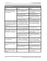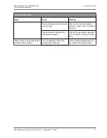
the leak must therefore be located and remedied if
there is:
–
Loss of the inert gas charge (delivery state),
–
Loss of the entire refrigerant charge
or
–
underfilling.
Lower refrigerant levels in the containers are due to
loss of refrigerant as a result of leaks. For this rea-
son, all pipes, connections and valve glands should
be checked regularly, especially in the initial period
of assembly.
The most striking feature if there is a leak in the filled
refrigerant circuit is the smell of refrigerant. The
odour threshold of ammonia in the air is approx. 5
ppm and thus well below the permitted MAK values.
Methods of leak detection:
–
Regular visual inspections.
–
Smudges/dirt stains indicate leaking
refrigerant/oil mixture.
–
Leak tests with nitrogen with a max. of 0.5%
ammonia by volume, an elapsed time of more
than 3 hours and application of a foaming agent
to all the joints with a brush. Oil-filled compres-
sors or circuit sections must only be charged
with nitrogen – not air – to generate pressure.
–
Use of an NH
3
leak detector.
–
Ammonia produces the following colours when
leak tests are performed:
–
Red litmus paper turns blue,
–
Blotting paper impregnated with phenolph-
thalein turns red (moisten).
Caution!
Due to the danger of explosion, oxy-
gen must never be used to build up
the pressure!
Generate a test pressure in the refrigerant circuit that
meets the intended operating pressure for the leak
tightness test to determine leaks on the refrigerant
side, e.g. in the case of escaped inert gas or refriger-
ant. When system parts are individually tested, the
maximum operating pressure indicated on the
respective system part for the corresponding pres-
sure chamber must not be exceeded. The use of
foaming agents gives the best results at test pres-
sures < 5 bar.
If leaks are determined, these must be sealed imme-
diately. Release the test pressure before beginning
repair! Evacuate the system after repairs are com-
plete and after rechecking for leaks.
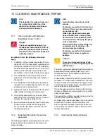
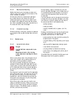
10.4.4.12
Venting the refrigerant circuit
When air penetrates the refrigerant circuit, this
makes itself felt in a fall-off in performance and the
manometer on the discharge side of the compressor
indicates a higher pressure compared to the conden-
sation temperature. Any leaks must be remedied. In
extreme cases, air in the circuit may interrupt the
flow of refrigerant and cause the oil cooling to fail.
There are several ways of venting the system. The
air or the NH
3
-air mixture is vented via the vent
valves of the condenser or the suction filter in water
filled vessels when the package is at a standstill.
If air is in the mixture, the venting ammonia is absor-
bed from water.
Hint!
Continuous venting using a Grasso
purger is recommended.
10.4.4.13
Refrigerant evacuation
Hint!
Shut the oil pump during evacuation!
The purpose of evacuating the system is to remove
air and moisture from the refrigerant circuit.
Evacuation is required:
–
after intervention in the refrigerant circuit and
elimination of leaks,
–
before the start-up/restarting.
Evacuate the screw compressor package using a
vacuum pump. The screw compressor must not be
used for evacuation.
During evacuation, all affected parts of the circuit
should be at room temperature at least because cold
parts hinder the removal of moisture.
If there is still any moisture in the screw compressor
package, this will lead to a rise in pressure. Evacua-
tion must continue until the pressure no longer
increases. A pressure comparison is based on a
constant ambient temperature.
Cleaning, maintenance, repair
Operating Manual | GEA Grasso M-Series
Screw Compressor Packages
80
GEA Refrigeration Germany GmbH | P_261511_1 | Generated 01.04.2015
Summary of Contents for Grasso M-Series
Page 88: ......

