Hint!
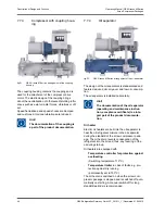
The discharge check valve can be inte-
grated into the oil separator for screw
compressor packages with discharge
side nominal diameters up to NB 150.
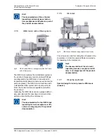
The suction filter prevents dirt particles carried by the
suction flow from penetrating into the compressor.
The filter element is characterized by a very large fil-
tering area. The filter fineness is 140 μm.
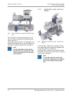
Gas vibrations which can arise in the pressure cham-
ber of compressors under high pressure conditions
in the range of zero delivery are prevented by a gas
vibration protection system. This comprises a pres-
sure compensation line between the oil separator
and the working chamber of the compressor.
7.10
Oil System
The screw compressors operate oil-flooded. During
the compression process, refrigerating machine oil is
supplied to the compressor for lubrication, sealing,
noise reduction, and absorption of part of the com-
pression heat. After the compression process, the oil
is separated again from the refrigerant in the oil sep-
arator.
7.10.1
Oil separation
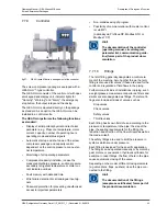
The refrigerant-oil mixture is led into the first part of
oil separator. The first part of the oil separator con-
sists of two chambers. The first chamber employs
gravity separation. The hot gas passes the demister
while flowing out of the first chamber into the second
chamber. The oil separated thereby is collected in
the second chamber. Both the chambers of the first
part of oil separator simultaneously serve as oil
receivers.
In the second part of the oil separator, the fine sepa-
ration of the aerosol oil portion from the refrigerant is
performed by means of replaceable fine oil separa-
tion cartridges. The oil separated in the fine separa-
tion part of the oil separator is returned to the com-
pressor via an additional orifice.
7.10.2
Oil heater
The oil heater on the oil separator is to be started
when the package is shut down in order to ensure a
minimum oil temperature and sufficient oil viscosity
required for restarting the package. The oil heating is
not regulated. The maximum temperature of the
heating rod is restricted.
7.10.3
Oil cooling
Before it is returned to the compressor for use, the
oil heated up in the compressor has to be cooled
down to a temperature at which it has sufficient vis-
cosity.
The following oil coolers are available:
1. liquid-cooled (non corrosive media)
–
water (non corrosive)
–
propylene glycol (25%)
–
ethylene glycol (35%)
–
Other refrigerants on request
2. Thermosiphon
3. Refrigerant injection
7.10.4
Oil filter
After cooling, the oil enters the oil filter which retains
solid particles from the entire oil flow.
Due to its large surface, the star-folded glass fibre
element has a high absorbing capacity and thus a
long operating lifetime. The filter has a relative filter
fineness of 25 µm.
7.10.5
Oil pump
The oil pump runs for pre- and during compressor
operation.
It draws the refrigeration compressor oil from the
receiver space in the oil separator, through the the
oil cooler and oil filter and pumps it to the bearings,
the balance piston, the shaft seal, to the capacity
control system and, if fitted, to the compressor's
hydraulic Vi adjustment system.
The oil pump pumps more oil than the compressor
uses. This surplus quantity of oil is returned to pump
suction via the spring loaded oil pressure regulating
valve. The oil pressure regulating valve regulates a
pressure difference between the oil pump discharge
side and the unit final pressure (according to the
value in the P+I diagram).
Description of Design and Function
Operating Manual | GEA Grasso M-Series
Screw Compressor Packages
46
GEA Refrigeration Germany GmbH | P_261511_1 | Generated 01.04.2015
Summary of Contents for Grasso M-Series
Page 88: ......

