


Chapter 7. PID Built-In Function Block
358
PACSystems* RX7i, RX3i and RSTi-EP CPU Programmer's Reference Manual
GFK-2950C
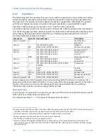
7.4.7
Sample Period and PID Function Block Scheduling
The PID function block is a digital implementation of an analog control function, so the
dt
sample
time in the PID Output equation is not the infinitesimally small sample time available with analog
controls. The majority of processes being controlled can be approximated as a gain with a first or
second order lag and (possibly) a pure time delay. The PID function block sets a CV output to the
process and uses the process feedback PV to determine an Error to adjust the next CV output. A key
process parameter is the total time constant, which is how fast the process can change PV when the
CV is changed. As discussed in
Determining the Process Characteristics
below, the total time
constant, T
p
+T
c
, for a first order system is the time required for PV to reach 63% of its final value
when CV is stepped. The PID function block will not be able to control a process unless its Sample
Period is well under half the total time constant. Larger Sample Periods will make it unstable.
The Sample Period should be no bigger than the total time constant divided by 10 (or down to 5
worst case). For example, if PV seems to reach about 2/3 of its final value in 2 seconds, the Sample
Period should be less than 0.2 seconds, or 0.4 seconds worst case. On the other hand, the Sample
Period should not be too small, such as less than the total time constant divided by 1000, or the Ki *
Error *
dt
term for the PID integral term will round down to 0. For example, a very slow process that
takes 10 hours or 36,000 seconds to reach the 63% level should have a Sample Period of 40 seconds
or longer.
Variations of the time interval between PID function solutions can have short-term effects on the CV
output. For example, if a step change to PV caused by measurement noise occurs between solutions,
the value of the derivative term will be inversely proportional to the time interval. The performance
of PID loops that are tuned for quick response may be improved when the solution interval is held
constant by configuring the CPU for constant sweep mode. Depending on the CPU model and the
application, constant sweep times of 10 ms, integer multiples of 10 ms, or exact divisors of 10 ms
(1, 2 or 5 ms) will be possible. The Sample Period can then be set for a suitable multiple of 10 ms.
If many PID loops are used, allowing the application to solve all the loops on the same sweep may
lead to wide variations in CPU sweep time. If the loops have a common Sample Period that is at least
equal to the number of PID loops times the sweep time, a simple solution is to sequence one or more
1’s through an array of zero‘s and use these bits to enable power flow to individual PID function
blocks. The logic should assure that each PID function block is enabled no more often than its Sample
Period.
Summary of Contents for PACSystems RSTi-EP
Page 357: ......
Page 466: ...Chapter 9 Diagnostics GFK 2950C February 2018 451 ...


