Chapter 2. Program Organization
22
PACSystems* RX7i, RX3i and RSTi-EP CPU Programmer's Reference Manual
GFK-2950C
Function Block Diagram
Function Block Diagram (FBD) is an IEC 61131-3 graphical programming language that represents
the behavior of functions, function blocks and programs as a set of interconnected graphical blocks.
FBD depicts a system in terms of the flow of signals between processing elements, in a manner very
similar to signal flows depicted in electronic circuit diagrams. Instructions are shown with inputs
entering from the left and outputs exiting on the right. A function block type name is always shown
within the element and the name of the function block instance is shown above the element.
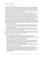
Solve Order
Instance of
UDFB, “Weight”
Instance of
UDFB, “Weight”
Wire indicates data flow
from output to input
Figure 12: Illustration of Function Block Diagram
The order of execution of instructions in an FBD is determined by the following:
a)
The display position of the instruction in the FBD editor
b)
Whether the inputs to the FBD instruction are resolved.
To determine the order of execution of FBD instructions in the FBD editor, the FBD compiler
performs the following steps:
1.
The FBD compiler scans the instructions in the FBD editor, beginning from left to right, and top to
bottom. When an instruction is encountered, the compiler attempts to resolve the instruction,
that is, the inputs are known. If the inputs are known, the instruction is solved, and scanning
continues for the next instruction.
2.
If the current instruction cannot be resolved, that is, the inputs are not known, then the compiler
scans for the previous instruction, using the wire connecting the output of the previous
instruction to the input of the current instruction.
3.
If the previous instruction can be resolved, the compiler calculates the output. The output of the
previous instruction then becomes the input to the current instruction, the current instruction is
resolved, and scanning continues for the next instruction.
4.
If the previous instruction cannot be resolved, that is, the inputs are not known, then step 2 is
repeated until an instruction is encountered, which can be resolved.
Summary of Contents for PACSystems RSTi-EP
Page 357: ......
Page 466: ...Chapter 9 Diagnostics GFK 2950C February 2018 451 ...


