Chapter 4. Ladder Diagram (LD) Programming
222
PACSystems* RX7i, RX3i and RSTi-EP CPU Programmer's Reference Manual
GFK-2950C
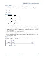
Timing diagram
ENABLE
Q
A
B
C
D
E
F
G
H
A.
ENABLE and Q both go high; timer is reset (CV = 0).
B.
ENABLE goes low; timer starts accumulating time.
C.
CV reaches PV; Q goes low and timer stops accumulating time.
D.
ENABLE goes high; timer is reset (CV = 0).
E.
ENABLE goes low; timer starts accumulating time.
F.
ENABLE goes high; timer is reset (CV = 0) before CV had a chance to reach PV. (The diagram is
not to scale.)
G.
ENABLE goes low; timer begins accumulating time.
H.
CV reaches PV; Q goes low and timer stops accumulating time.
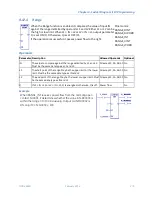
Operands for OFDT
Warning
Do not use the Address, 1, or 2
addresses with other instructions. Overlapping
references cause erratic timer operation.
Parameter Description
Allowed Operands Optional
Address
(????)
The beginning address of a three-word WORD array:
Word 1: Current value (CV)
Word 2: Preset value (PV)
Word 3: Control word
R, W, P, L, symbolic No
PV
The Preset Value, used when the timer is enabled or reset.
0
PV
+32,767. If PV is out of range, it has no effect on Word 2.
All except S, SA, SB,
SC
Optional
CV
The current value of the timer.
All except S, SA, SB,
SC, constant
Optional
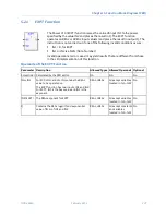
Example for OFDT
The output action is reversed by the use of a negated output
coil. In this circuit, the OFDT timer turns off negated output coil
%Q0001 whenever contact %I0001 is closed. After %I0001
opens, %Q0001 stays off for 2 seconds then turns on.
Summary of Contents for PACSystems RSTi-EP
Page 357: ......
Page 466: ...Chapter 9 Diagnostics GFK 2950C February 2018 451 ...


