background image

GE H

EALTHCARE

O

PTIMA

 XR200

AMX

/XR220

AMX


D

IRECTION

 5336113-1EN, R

EVISION

 10

I

NSTALLATION

 M

ANUAL

Preface

Page 3

Important information

WARNING

(EN)

This service manual is available in English only.

If a customer's service provider requires a language other than English, it is the customer's 

responsibility to provide translation services.

Do not attempt to service the equipment unless this service manual has been consulted and is 

understood.

Failure to heed this warning may result in injury to the service provider, operator or patient from 
electric shock, mechanical or other hazards.

ПРЕДУПРЕЖДЕНИЕ

(BG)

T

ова


упътване


за


работа


е


налично


само


на


английски


език

Ако


доставчикът


на


услугата


на


клиента


изиска


друг


език

задължение


на


клиента


е


да


осигури


превод

.

Не


използвайте


оборудването

преди


да


сте


се


консултирали


и


разбрали


упътването


за


работа

.

неспазването


на


това


предупреждение


може


да


доведе


до


нараняване


на


доставчика


на


услугата

оператора


или


пациент

в


резултат


на


токов


удар

механична


или


друга


опасност

.

警告

(ZH-CN)

本维修手册仅提供英文版本。

如果客户的维修服务人员需要非英文版本,则客户需自行提供翻译服务。

未详细阅读和完全理解本维修手册之前,不得进行维修。

忽略本警告可能对维修服务人员、操作人员或患者造成电击、机械伤害或其他形式的伤

害。

警告

(ZH-HK)

本服務手冊僅提供英文版本。
• 倘若客戶的服務供應商需要英文以外之服務手冊,客戶有責任提供翻譯服務。
• 除非已參閱本服務手冊及明白其內容,否則切勿嘗試維修設備。
• 不遵從本警告或會令服務供應商、網絡供應商或病人受到觸電、機械性或其他的危險。

警告

(ZH-TW)

本維修手冊僅有英文版。
• 若客戶的維修廠商需要英文版以外的語言,應由客戶自行提供翻譯服務。
• 請勿試圖維修本設備,除非 您已查閱並瞭解本維修手冊。
• 若未留意本警告,可能導致維修廠商、操作員或病患因觸電、機械或其他危險而受傷。

UPOZORENJE

(HR)

Ovaj servisni priru

č

nik dostupan je na engleskom jeziku.

Ako davatelj usluge klijenta treba neki drugi jezik, klijent je dužan osigurati prijevod.

Ne pokušavajte servisirati opremu ako niste u potpunosti pro

č

itali i razumjeli ovaj servisni 

priru

č

nik.

zanemarite li ovo upozorenje, može do

ć

i do ozljede davatelja usluge, operatera ili pacijenta uslijed 

strujnog udara, mehani

č

kih ili drugih rizika.

VÝSTRAHA

(CS) 

Tento provozní návod existuje pouze v anglickém jazyce.

V  p

ř

ípad

ě

, že externí služba zákazník

ů

m pot

ř

ebuje návod v jiném jazyce, je zajišt

ě

ní p

ř

ekladu do 

odpovídajícího jazyka úkolem zákazníka.

Nesnažte se o údržbu tohoto za

ř

ízení, aniž byste si p

ř

e

č

etli tento provozní návod a pochopili jeho 

obsah.

V  p

ř

ípad

ě

 nedodržování této výstrahy m

ů

že dojít k poran

ě

ní pracovníka prodejního servisu, 

obslužného personálu nebo pacient

ů

 vlivem elektrického proudu, respektive vlivem mechanických 

č

i jiných rizik.

ADVARSEL

(DA)

Denne servicemanual findes kun på engelsk.

Hvis en kundes tekniker har brug for et andet sprog end engelsk, er det kundens ansvar at sørge 

for oversættelse.

Forsøg ikke at servicere udstyret uden at læse og forstå denne servicemanual.

Manglende overholdelse af denne advarsel kan medføre skade på grund af elektrisk stød, 

mekanisk eller anden fare for teknikeren, operatøren eller patienten.

Summary of Contents for Optima XR200amx

Page 1: ...GE Healthcare Optima XR200amx XR220amx Installation Manual Direction 5336113 1EN Revision 10 Front cover ...

Page 2: ...ined in Annals Number 26 of the ICRP and with applicable national standards ATENCION LOS APARATOS DE RAYOS X SON PELIGROSOS PARA EL PACIENTE Y EL MANIPULADOR CUANDO LAS NORMAS DE PROTECCION NO ESTAN OBSERVADAS Aunque este aparato está construido según las normas de seguridad más estrictas la radiacion X constituye un peligro al ser manipulado por personas no autorizadas o incompetentes Una explosi...

Page 3: ...受到觸電 機械性或其他的危險 警告 ZH TW 本維修手冊僅有英文版 若客戶的維修廠商需要英文版以外的語言 應由客戶自行提供翻譯服務 請勿試圖維修本設備 除非 您已查閱並瞭解本維修手冊 若未留意本警告 可能導致維修廠商 操作員或病患因觸電 機械或其他危險而受傷 UPOZORENJE HR Ovaj servisni priručnik dostupan je na engleskom jeziku Ako davatelj usluge klijenta treba neki drugi jezik klijent je dužan osigurati prijevod Ne pokušavajte servisirati opremu ako niste u potpunosti pročitali i razumjeli ovaj servisni priručnik zanemari...

Page 4: ...é et compris Le non respect de cet avertissement peut entraîner chez le technicien l opérateur ou le patient des blessures dues à des dangers électriques mécaniques ou autres WARNUNG DE Diese Serviceanleitung existiert nur in englischer Sprache Falls ein fremder Kundendienst eine andere Sprache benötigt ist es Aufgabe des Kunden für eine entsprechende Übersetzung zu sorgen Versuchen Sie nicht dies...

Page 5: ...Jei nepaisysite šio įspėjimo galimi paslaugų tiekėjo operatoriaus ar paciento sužalojimai dėl elektros šoko mechaninių ar kitų pavojų ADVARSEL NO Denne servicehåndboken finnes bare på engelsk Hvis kundens serviceleverandør har bruk for et annet språk er det kundens ansvar å sørge for oversettelse Ikke forsøk å reparere utstyret uten at denne servicehåndboken er lest og forstått Manglende hensyn ti...

Page 6: ...sluhu zariadenia kým si neprečítate návod na obluhu a neporozumiete mu Zanedbanie tohto upozornenia môže spôsobiť zranenie poskytovateľa služieb obsluhujúcej osoby alebo pacienta elektrickým prúdom mechanické alebo iné ohrozenie ATENCION ES Este manual de servicio sólo existe en inglés Si el encargado de mantenimiento de un cliente necesita un idioma que no sea el inglés el cliente deberá encargar...

Page 7: ... GE Healthcare WPA and WPA2 are trademarks of the Wi Fi Alliance All other products and their name brands are trademarks of their respective holders COPYRIGHTS All material copyright 2011 by General Electric Company Inc All rights reserved The material presented and contained herein may not be reproduced in any form or manner without the written permission of General Electric Company Inc ...

Page 8: ...wn specially trained field engineers All of GE s electrical work on these products will comply with the requirements of the applicable electrical codes The purchaser of GE equipment shall only utilize qualified personnel i e GE s field engineers personnel of third party service companies with equivalent training or licensed electricians to perform electrical servicing on the equipment IMPORTANT X ...

Page 9: ...care sales or service representatives GE personnel please use the GE Healthcare complaint handling process to report all omissions errors and defects in this publication DANGER Risk of Explosion Danger of explosion if battery is incorrectly replaced Replace only with the same or equivalent type recommended by the manufacturer Discard used batteries according to the manufacturer s instructions ATTE...

Page 10: ...nload procedure to Chapter 3 Section 3 6 4 Refer to SPR HCSDM00157822 6 02AUG2013 Chapter 3 Section 3 5 2 added Notice about potential test equipment damage Refer to HCSDM00188252 Chapter 4 Sections 4 10 3 1 and 4 10 3 2 added Notice regarding reset of system after DAP is reconnected Refer to HCSDM00188256 Chapter 3 Section 3 6 3 added Caution message regarding wall plug Refer to TrackWise 1083113...

Page 11: ...tion requirement Chapter 4 Section 4 8 Section 4 9 Section 4 13 added notes regarding consulting your administrator for Account and Password information Chapter 4 Section 4 10 4 added tablet holder assembly installation procedure Chapter 8 added task regarding special login and user management account and password creation to system administrator added task regarding providing account and password...

Page 12: ...GE HEALTHCARE OPTIMA XR200AMX XR220AMX DIRECTION 5336113 1EN REVISION 10 INSTALLATION MANUAL Page 12 Preface ...

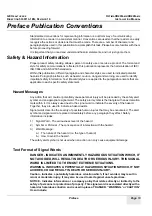
Page 13: ...y alert symbol and an appropriate signal word The safety alert symbol is the triangle with an exclamation mark within it It Is always used next to the signal word to indicate the severity of the hazard Together they are used to indicate a hazard exists Signal words describe the severity of possible human injures that may be encountered The alert symbol and signal word are placed immediately before...

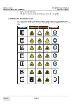
Page 14: ... in this publication These graphical icons symbols may be used to make you aware of specific types of hazards that could possibly cause harm keep_up fragile static_elec keep_dry general torque ce magnetic impact heat pinch explosive crush mechanical poisonmatl biohazard corrosive general radiation electrical tipping entanglement compressgas heavyobject laser flammable Read Manual ppe respitory ppe...

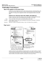
Page 15: ...information possibly stated previously Comment Represents additional information that may or may not be relevant to your situation Page Layout Headers and footers in this publication are designed to allow you to quickly identify your location The document part number and revision number appears in every header on every page Odd numbered page footers indicate the current chapter its title and curre...

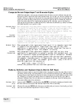
Page 16: ...Fixed Input This paragraph s font represents fixed input It is computer input that is typed in via the keyboard Typed input that does not vary from application to application or system to system Fixed text the user is required to supply as input For example cd usr 3p Example Variable Input This paragraph s font represents computer input that can vary from application to application or system to sy...

Page 17: ...nstallation process 33 Section 3 2 Unpacking the system 34 Section 3 3 Replacing the electrical plug 35 Section 3 4 Turning on the system 35 Section 3 5 Ground and leakage testing 37 3 5 1 Performing ground resistance testing 37 3 5 1 1 Gathering test equipment 37 3 5 1 2 Attaching test cables 38 3 5 1 3 Setting test parameters 40 3 5 1 4 Performing zero adjustment 41 3 5 1 5 Taking ground measure...

Page 18: ... 2 6 2 Configuring broadcast SSID networks 61 4 2 6 3 Configuring non broadcast SSID networks 62 4 2 6 4 Troubleshooting connections 63 4 2 7 Options configuration 64 4 2 8 InSite configuration 64 4 2 9 PNF configuration 64 4 2 9 1 PNF GUI Control area 64 4 2 9 2 PNF tabs and parameters 65 4 2 10 Time Server configuration 66 4 2 11 Secure Login configuration 66 Section 4 3 Changing Auto Protocol A...

Page 19: ...ng the wireless exposure handswitch 89 Section 4 11 Importing custom IP looks from Definium AMX 700 99 Section 4 12 Enabling Advanced Service mode 100 Section 4 13 IP Address Change Procedure 100 4 13 1 Snapshot Tool Configuration 101 Chapter 5 Calibration 111 Section 5 1 Saving changes 111 Section 5 2 Detector calibration 111 Section 5 3 Image quality calibration 111 5 3 1 Calibrating the printer...

Page 20: ...ION 10 INSTALLATION MANUAL Page 20 Table of Contents Chapter 6 Detector checks and QAP 119 6 0 1 Detector check 119 6 0 2 QAP checkout 119 Chapter 7 Certified components 121 Section 7 1 Component rating plates 121 Chapter 8 Final tasks 127 Section 8 1 Final tasks 127 ...

Page 21: ...1 1 Energy source Yes No Location of energy isolating means Magnitude of energy Electrical Yes AC power plug 120 VAC 60Hz 220 VAC 50Hz Electrical Yes Circuit breaker 156VDC Electrical batteries Yes Battery board connector J1 156VDC Pneumatic No n a n a Hydraulic No n a n a Gas water steam No n a n a Chemical No n a n a Mechanical motion No n a n a Gravity No n a n a Rear suspension spring No n a n...

Page 22: ...uthorized to perform LOTO Those trained in LOTO Title of affected employees and how to notify Hospital personnel notified by verbal communication 1 2 1 Preparing for LOTO 1 Have this equipment on hand Safety glasses Voltage meter LOTO kit 5421892 contains see Figure 1 1 3 brass padlocks and identification labels 3 LOTO tag packages 25 tags per package 1 electrical plug lockout device 110V for AC p...

Page 23: ...0AMX DIRECTION 5336113 1EN REVISION 10 INSTALLATION MANUAL Chapter 1 Safety Page 23 2 Locate the AC power plug E1 system circuit breaker E2 and battery connectors E3 See Figure 1 2 Figure 1 2 Electrical energy lockout locations E2 E1 E3 ...

Page 24: ...it for several seconds until the power button light ring turns blue indicating that the system is shutting down 4 When the power light ring begins to blink blue indicating that the system is in standby switch the circuit breaker E2 to the OFF position See Figure 1 3 Figure 1 3 Circuit breaker E2 in OFF position 5 Unplug the power cord from the wall outlet 6 Apply an approved AC power plug locking ...

Page 25: ...o green battery power connectors J3 and J4 and the two sense connectors J13 and J14 from the Cricket board Apply a locking device then apply your personal red lock and tag See Figure 1 5 Figure 1 5 Battery connectors J3 J4 J13 J14 and locking device Item Description 1 Battery power connectors J3 J4 2 Battery sense connectors J13 J14 1 2 ...

Page 26: ... J11 and J12 from the Cricket board Apply a locking device then apply your personal red lock and tag See Figure 1 6 Figure 1 6 Battery connectors J1 J2 J11 J12 and locking device 10 Press the power button and verify that the system does not turn on 11 Verify that the voltage meter is working properly by testing it on a known live voltage source such as a wall outlet Item Description 1 Battery powe...

Page 27: ...ERVISOR 13 Perform the necessary service or repair 1 2 3 Returning system to service 1 Notify affected personnel that LOTO devices are being removed and equipment is being re energized 2 Verify that the area is safe to re energize the equipment 3 Verify that any safety guards or devices have been reinstalled and replace all guards and covers as necessary 4 Remove tools and all non essential equipm...

Page 28: ...onents If you are using a static mat or wrist strap be sure to connect the mat and strap to machine ground not earth ground This is necessary to isolate yourself from earth ground and equalize your potential with the machine ESD damage prevention includes these steps 1 Perform LOTO 2 Verify that the AC plug is not connected to an energy source outlet 3 Connect ground mat and wrist strap assembly t...

Page 29: ...acticing ESD procedures Use the following equipment to prevent static electricity damage to equipment Wrist straps are flexible straps with a maximum of one megohm 10 resistance in the ground cords To provide a proper ground wear the strap against bare skin The ground cord must connect snugly into the banana plug connector on the grounding mat or workstation Heel toe and boot straps can be used at...

Page 30: ...bly aids and Styrofoam 1 3 5 Recommended materials and equipment ELECTRICAL SHOCK HAZARD This section defines a workzone that is not connected to the system under service The mobile system is a battery powered unit that can deliver lethal current Ensure you are not providing an earth ground path when practicing ESD procedures Materials and equipment that are recommended for use in preventing stati...

Page 31: ...p tether for digital detector Optima XR220amx only Service keyboard Software CD External CD DVD ROM drive Operating System firmware USB drive Tablet holder assembly optional Optima XR220amx and Optima XR200amx Shipped separately DAP meter standard with Optima XR220amx optional for Optima XR200amx Digital detector Optima XR220amx only Detector batteries Optima XR220amx only Detector battery charger...

Page 32: ...GE HEALTHCARE OPTIMA XR200AMX XR220AMX DIRECTION 5336113 1EN REVISION 10 INSTALLATION MANUAL Page 32 Section 2 1 System components Figure 2 1 Optima systems Optima XR200amx Optima XR220amx ...

Page 33: ...on page 37 4 Power on and plug in the system Section 3 4 Turning on the system on page 35 5 Install the digital detector Section 3 6 Installing the digital detector on page 50 Optima XR220amx only 6 Install hardware options such as the DAP meter or barcode reader Section 4 10 Installing hardware options on page 74 7 Apply local language labels Section 3 7 Applying local language labels on page 56 ...

Page 34: ...d on its own wheels with minimal packaging External to the United States the Optima XR200amx Optima XR220amx is shipped in a packing crate To prepare the unit for installation follow these steps SYSTEM INSTALLATION WORKFLOW Upack the system Does the power plug meet requirements No Yes Ready for configuration and calibration Replace the power plug Plug in and turn on system power Install optional h...

Page 35: ...d replace it with the appropriate hospital grade plug as dictated by local regulations The replacement electrical plug must meet the following electrical specifications Hospital grade plug 100 240 VAC 1440 VA 50 60 Hz To replace the plug 1 Remove the three cross recessed screws that hold the plug together 2 Remove the plug 3 Remove the cross recessed screw holding the wires to the plug 4 Attach th...

Page 36: ...0amx XR220amx system 3 Check the battery level indicated by the battery symbol on the interface In the figure below the battery shows 25 capacity and discharging status Figure 3 3 Battery icon discharging 4 If battery charging is needed plug the system in to an electrical outlet 5 The icon changes to indicate that the battery is charging In the figure below the battery shows 40 capacity and chargi...

Page 37: ...ioki 3157 grounding tester or equivalent For sites in Europe use the cables that are provided with the Hioki tester For sites outside of Europe obtain the following Two green yellow ground stranded wire cables Cable A 2 5 mm 12 AWG 3 m 9 8 ft Cable B 2 5 mm 12 AWG 5 m 16 4 ft Two lugs to fit 0 64 cm 0 25 in terminals to the meter end of each cable Figure 3 5 Two clamps to fit onto the other end of...

Page 38: ...d the voltage measurement Sense terminal knob bottom right by turning them counterclockwise 2 Connect Cable B to the current output knob 3 Connect the short bar between the current output and voltage measurement knobs as shown in Figure 3 6 Figure 3 6 Test Cable B and short bar installation 4 Turn the two knobs clockwise to tighten 5 Loosen the other current output Source terminal top left attach ...

Page 39: ...GE HEALTHCARE OPTIMA XR200AMX XR220AMX DIRECTION 5336113 1EN REVISION 10 INSTALLATION MANUAL Chapter 3 Installation Page 39 Figure 3 7 Cable A Cable B and short bar connections ...

Page 40: ... the output current The value changes in 0 1 A increments To change the value by 1 0 A increments press or button C Press the button again to move to each of the other settings Maximum Test Value Timer and Frequency D Use the or buttons as needed to adjust the values E Press Figure 3 8 Test parameter value settings 3 While in the ready state press the buttons to display the Optional function setti...

Page 41: ...the 0ADJ indicator begins flashing below the resistance value and the zero adjustment begins During the zero adjustment a preset current is output through the shorted leads When zero adjustment is complete about three seconds the unit enters the ready state and the 0ADJ lamp lights If the test cables are too resistive the offset cannot be set Use less resistive cables and try to set the offset aga...

Page 42: ...GE HEALTHCARE OPTIMA XR200AMX XR220AMX DIRECTION 5336113 1EN REVISION 10 INSTALLATION MANUAL Page 42 Section 3 5 Ground and leakage testing Figure 3 11 Tester during and after zero adjustment ...

Page 43: ...put current 25 0 A or 30 0 A and the timer value decreases from 5 0 seconds to 0 0 seconds If the test passes the green Pass indicator is displayed Record the displayed resistance value in Table 3 3 5 Press Stop 6 Move cable B to the next measurement Table 3 3 then repeat steps 4 and 5 The voltage must not exceed 2 5 V 0 1 ohms Table 3 3 Ground measurement test points Component Measurement point M...

Page 44: ...E HEALTHCARE OPTIMA XR200AMX XR220AMX DIRECTION 5336113 1EN REVISION 10 INSTALLATION MANUAL Page 44 Section 3 5 Ground and leakage testing Figure 3 12 Tube test points Figure 3 13 Collimator test points ...

Page 45: ...HEALTHCARE OPTIMA XR200AMX XR220AMX DIRECTION 5336113 1EN REVISION 10 INSTALLATION MANUAL Chapter 3 Installation Page 45 Figure 3 14 Column test point Figure 3 15 Rear bin accessory access cover test point ...

Page 46: ...GE HEALTHCARE OPTIMA XR200AMX XR220AMX DIRECTION 5336113 1EN REVISION 10 INSTALLATION MANUAL Page 46 Section 3 5 Ground and leakage testing Figure 3 16 Tube latch test point ...

Page 47: ... if required see 3 5 1 Performing ground resistance testing on page 37 2 Ensure that all system covers are installed 3 Obtain a Dale 601 601E test meter or equivalent Perform leakage testing under the five specific conditions outlined in Table 3 4 Table 3 4 Leakage current test conditions Condition Power Test meter outlet X ray on Section reference 1 Off Normal No 3 5 2 1 Condition 1 Power off nor...

Page 48: ...m NORMAL to REVERSED or REVERSED to NORMAL Failure to do so can result in the internal test meter failure and tripping of facilities circuit breakers 3 5 2 1 Condition 1 Power off normal outlet X ray off 1 Turn off the system power main circuit breaker ON On the test meter set the Function switch to ENCLOSURE LEAKAGE the L2 switch to CLOSED the Outlet switch to Normal and the M A P Lift Gnd to OFF...

Page 49: ... high readings by checking for damaged ground wire or internal system wiring that could be causing current to flow to the tested component or chassis Table 3 5 Leakage current test results 3 5 2 2 Condition 2 Power off reversed outlet X ray off 1 On the test meter set the Outlet switch to Reversed 2 Verify the system power is OFF main circuit breaker ON 3 Using the clamp connect to all conductive ...

Page 50: ...p to connect to all conductive surfaces Table 3 6 Exposure technique 4 Record the readings in Table 3 5 Section 3 6 Installing the digital detector The digital detector is for use only with the Optima XR220amx or Optima XR200amx with digital upgrade The digital detector uses a wireless signal to communicate with the system The detector contains a docking mechanism that provides charging power when...

Page 51: ...g There are three boxes inside each other to give maximum detector protection 1 Locate the detector shipping box See Figure 3 19 Figure 3 19 Detector shipping box 2 Inspect the box for physical or water damage If present document the damage 3 Remove all four clips and lift top of outer box from bottom Instructions are printed on the outside of the box 4 Lift the plastic bag and inner box out of th...

Page 52: ...btain and install a computer style power cord with a CE approved IEC 60320 1 C13 style connector on one end and the locally appropriate wall plug connector on the other The cord must meet or exceed the following electrical specification AC 120 240V 50 60 Hz 130VA 168VA 1 4 Amps Do not modify the shipped US style cord as this can present a shock hazard to the user The detector is delivered with two...

Page 53: ...e tether Verify that there is no damage 2 Remove the battery if present 3 Connect the backup tether to the detector Figure 3 23 Figure 3 23 Connecting the tether to the detector Battery LED status Meaning Green green Battery more than 75 remaining Off green Battery remaining between 25 and 75 Off yellow Battery remaining between 10 and 25 Off red Battery less than 10 remaining Off off Detector in ...

Page 54: ... Select DET DATA DOWNLOAD link 10 Select the appropriate detector 11 Follow the on screen instructions 3 6 6 Detector registration The first time a detector is used with an Optima XR220amx or Optima XR200amx with digital upgrade it must be registered with that system During registration the detector must be connected to the system using the backup tether 3 6 4 Connecting the backup tether on page ...

Page 55: ...the detector See Figure 3 24 Figure 3 24 Detector grid 3 6 8 1 Unpacking and inspecting the grid Inspect the surface of the grid inside surface of the grid holder for any signs of damage incurred during shipment Look for signs of scuffing abrasions or dents The patient contact side of the grid holder is covered with a padded overlay Inspect it for any signs of scrapes or tears Check the perimeter ...

Page 56: ...attached improperly the system alerts the user with a double beep and displays a message on the status bar Section 3 7 Applying local language labels Each Optima XR200amx XR220amx system must be labeled with the appropriate X ray warning label in the local language The system is delivered with an English label applied Figure 3 25 English X ray warning label If the system is located at a site where...

Page 57: ...A software install resets all configuration data If the system configuration files are restored you do not need to re configure the system After adding purchased options Installation of purchased options can only be performed by an authorized GE Healthcare service representative If you add purchased options to the system update the system configuration files immediately and create and save a new b...

Page 58: ...ddress of site where system is installed Street Address 2 Street address continued of site where system is installed City City where system is installed State Province State or province where system is installed Postal Code Postal or ZIP code where system is installed Department Name Department name for example Radiology responsible for system maintenance Telephone Phone number of department respo...

Page 59: ...Gateway Fixed Only Default gateway Enabled only if Wired IP Settings is set to Static Static DNS Server 1 Site domain name server Enabled only if Wired IP Settings is set to Static Static DNS Server 2 Site domain name server Enabled only if Wired IP Settings is set to Static AE Title Fixed Only Application Entity Title for DICOM Fixed value Port Number Fixed Only Software port used for network com...

Page 60: ...n minutes Image Mask Adjustment Optima XR220amx or Optima XR200amx with digital upgrade Adjust the mask that is applied to the acquired image from the detector Options 3mm 2mm 1mm 0 1mm 2mm 3mm Table 4 4 General tab parameters Parameter Definition Table 4 5 Hardware tab parameters Parameter Definition Collimator Light Maximum On Time Time in seconds that the collimator light will remain on Collima...

Page 61: ...n the Certificates tab a Observe the USB flashdrive resident certificates in the pull down list next to the ADD button b If there is more than one certificate you will need to select each certificate individually c Click ADD to install the displayed certificate from the drop down list 6 Continue with the site specific configurations as defined by the IT administrator 7 Exit the Configuration utili...

Page 62: ...etwork by a static IP address select STATIC IP and enter the IP address netmask and gateway If no gateway is used you must enter 0 0 0 0 If the system will be identified on the network using DHCP select DHCP 3 Enter the network SSID 4 Choose the authentication type WPATM Enterprise EAP Encryption if different than TKIP Identity Password Client certificate Inner Auth Private key file Private key pa...

Page 63: ...Troubleshooting connections If you try to connect in an enterprise situation it will continue to try to connect until you tell it to stop by selecting DISCONNECT Table 4 8 Authentication type Required fields No FIPS FIPS ON Static WEP Shared Key authentication WEP keys Y N WPATM Personal PSK Encryption if different than TKIP PSK Y N WPATM Enterprise EAP Encryption if different than TKIP Identity P...

Page 64: ...L ON When the firewall is off all network traffic in both directions is allowed This setting is used primarily for troubleshooting When the firewall is on it allows only the network communications that are specified by its configuration and rejects all the rest After modifying any PNF options select RESTART FIREWALL to apply the changes 4 2 9 1 PNF GUI Control area The PNF GUI Control area near th...

Page 65: ...a range of IP addresses or a masked subnet Allowed IPs Lists current filters by IP Remove Existing Filters Select the Delete box checkbox next to the filter to delete then select DELETE EXISTING FILTERS Add New Filter In the Allowed IPs field specify a particular IP address a range of IP addresses or a masked subnet Select ADD FILTER to apply your changes DICOM tab Used to add DICOM port numbers a...

Page 66: ... Name Source IP Dest IP Lists current filters by name source IP destination IP destination port and protocol Remove Existing Filters Select the Delete box checkbox next to the filter to delete then select DELETE EXISTING FILTERS Add New Filter In the Name field specify the filter name In the Source IP field specify the source IP In the Destination IP field specify the destination IP In the Destina...

Page 67: ...stem 2 On the Applications desktop press the UTILITIES button 3 On the Utilities desktop next to Network Connections press EDIT 4 On the Network Connections window in the Network Hosts section press ADD The Add Network Host screen appears Port Number Port number used to communicate with primary audit server Protocol Protocol used to communicate with primary audit server TCP UDP Send Test Message T...

Page 68: ...Type of information the host will provide upon query from another host Options are No provider Study and Patient Storage Commitment Available only on the Optima XR220amx or Optima XR200amx with digital upgrade system Designates whether the host will store image data Storage Commitment Application Entry Title if Storage Commitment is Yes Available only on the Optima XR220amx or Optima XR200amx with...

Page 69: ...der to be displayed by PACS Leaving this option unselected sends all available VOI LUTs to the DICOM header for PACS to query and apply Note PACS should be configured to read the first VOI LUT for proper display of images on the Acquisition workstation Send MPPS N Create and N Set notification to this network host Available only on the Optima XR220amx or Optima XR200amx with digital upgrade system...

Page 70: ... If the problem persists contact the technical support group or system administrator 4 4 1 3 Removing network hosts Follow these instructions to remove a network host 1 On the Applications desktop press the UTILITIES button 2 On the Utilities desktop next to Network Connections press EDIT 3 On the Network Connections window in the Network Hosts section select the network host connection to delete ...

Page 71: ...ion Area for notes about the printer or configuration Density Min Minimum density range Density Max Maximum density range Magnification Type Options are Replicate Bilinear Cubic None Smooth Factor Image smoothing factor Trim Designates whether there is to be trim Yes or No Polarity Options are Normal Reverse Border Density Color of the image border Options are Black White Empty Image Density Color...

Page 72: ...rs let the site control how images will be handled after acquisition including printing archiving and deleting For more information about image management parameters including Auto Print Auto Send sometimes called Auto Push and Auto Delete refer to the Optima XR220amx or Optima XR200amx with digital upgrade Operator Manual Section 4 6 Image processing 4 6 1 Enabling EMI reduction The EMI Reduction...

Page 73: ...be copied to destination name Select OK to confirm 6 Press OK 7 Open the exams from the Local database If the exams are being viewed on a computer that has the DICOM viewer installed images may be viewed directly from the disk Section 4 8 Installing the Operator Manual Optima XR220amx and Optima XR200amx with digital upgrade systems only Note To install the Operator Manual OM you need the Account ...

Page 74: ...ormation please consult your administrator Note Except the login and user management account and password created specially to the system administrator GE field engineers also need to provide the related account and password information to system administrator for the below configuration Installing the Operator Manual Account xruser Password 4 xray IP Address Change Procedure Account su Password s...

Page 75: ...ystem manual Replacement Procedures Top cover removal 3 Remove the two screws from the inside of the left drive handle support then remove the cover See Figure 4 2 Figure 4 2 Left drive handle screws and cover 4 Route the USB cable through the opening in the bottom of the left drive handle support See Figure 4 3 Note You may need to loosen the detector bin mounting screws to provide clearance for ...

Page 76: ...UAL Page 76 Section 4 10 Installing hardware options Figure 4 3 Cable access hole and receiver placement on system 5 Attach the USB receiver to the plastic clip with the barcode facing out as shown in Figure 4 3 6 Plug the USB cable into a USB port on the PC See Figure 4 4 Cable access hole ...

Page 77: ...o you want to connect to a bluetooth SPP appears The user needs to select YES or the barcode reader functionality will not be enabled 4 10 1 3 Barcode reader LED indicators By default the OPI 4002 scanner is in power saving mode To turn it on press the trigger key for a few seconds If the scanner is not in use for a while it will go into sleep mode and the trigger key must be pressed for a few sec...

Page 78: ... additional configuration options 4 10 2 1 Setting to default configuration 1 Turn on the system Wait until the green LED on the barcode reader receiver starts flashing 2 Press the barcode reader trigger to start the scan 3 Scan the Reset To Default barcode Figure 4 6 Reset to Default barcode You will hear three quick sets of high low high beeps Whenever you scan the Reset To Default barcode resca...

Page 79: ...o you can scan the necessary barcodes If you make a mistake during this configuration start over at step 1 1 Power up the system Wait until the green LED on the receiver starts flashing 2 Perform 4 10 2 1 Setting to default configuration on page 78 3 Scan the barcodes shown in Figure 4 7 top to bottom After scanning each barcode you will hear one set of high low high beeps The scanner will beep at...

Page 80: ...s Figure 4 8 Strip first two and last four characters and add a Tab suffix 4 10 2 6 Verifying optional configuration 2 1 Turn on the system Wait until the login screen appears 2 Verify that a green LED is blinking on the barcode reader receiver 3 Scan any barcode You will hear one set of high low beeps The scanned barcode characters appear in the Login ID field on the login screen with the first t...

Page 81: ...support Hot Swapping Failure to reset the system in this occurrence can result in an inaccurate dose value reported by the DAP meter 6 Perform DAP calibration See the System Manual Calibration Chapter Hardware Calibration DAP Calibration section for calibration procedure 4 10 3 2 DAP installation for Optima XR200amx system 1 Shut down the system and turn off the main circuit breaker 2 Remove the s...

Page 82: ...ies to hold the cable in position but do not tighten them until range of motion is confirmed Leave enough extra cable length at the DAP meter so that the tube collimator assembly can be moved through the normal range of motion without unplugging the cable c Route the DAP cable through the cable access opening in the right front cover See Figure 4 11 d Remove the HV cable clamp mounting screws See ...

Page 83: ...ttached to J6 on bulkhead 7 Confirm that there is sufficient slack in the DAP cable at the tube collimator assembly a Move the tube collimator assembly through the full range of motion and verify that the DAP cable remains connected to the DAP meter b Once sufficient cable slack is confirmed tighten down the cable ties to secure the DAP cable to the existing cable drape 8 Arrange the cable bundle ...

Page 84: ...le bundle See the System manual Replacement Procedures chapter Cable Cover Installation section 14 Configure the system to enable the DAP meter option See 4 2 7 Options configuration on page 64 15 Once the DAP meter option has been enabled it must be switched on at the Applications level a On the Applications desktop click the UTILITIES button b On the Utilities desktop select PREFERENCES OPTIONS ...

Page 85: ...the System Manual Calibration Chapter Hardware Calibration DAP Calibration section for calibration procedure 4 10 4 Installing the tablet holder assembly When the tablet holder is on hand contact a GE service representative to install the tablet holder assembly 1 Shut down the system and turn off the main circuit breaker 2 Unpack the tablet holder assembly 3 Remove the 4 screws on the lead apron h...

Page 86: ...r i e Loctite 243 to the 4 tablet holder assembly mounting screws new item 1 and tighten the screws Torque to 3 2 N m 2 36 lbft Figure 4 15 Installing the tablet holder assembly 5 Unlock the tablet clamp assembly with the key 6 Lift up the top cover of the tablet holder clamp Item Description 1 Tablet holder assembly mounting screws 4 2 Tablet holder assembly 3 Lead apron hanger 1 2 3 lock ...

Page 87: ...lder and make sure the tablet is clamped well After you turn the key to lock the clamp please check the back of the tablet clamp assembly to make sure the tablet is well fixed by the clamp without any possibility to fall down from the holder See below figures 8 Lock the tablet clamp assembly with the key and remove the key Front Back Not Clamped Well Clamped ...

Page 88: ...NSTALLATION MANUAL Page 88 Section 4 10 Installing hardware options 9 Tablet holder assembly functional check a Tilt the tablet holder from 10 to 10 b Rotate the tablet holder from 0 to 90 c Pull the handle on the tablet holder assembly to relax it from the column Tablet Lock ...

Page 89: ... the wired handswitch on the system as a backup 1 Remove both side covers and the top cover See System manual 5336122 1EN Chapter 8 Section 8 1 2 Top cover removal 2 Identify the components of the kit shown below Table 4 16 Figure 4 16 Figure 4 17 Table 4 16 Wireless handswitch kit 5503600 Part Number Description 5503600 Wireless Handswitch kit contains the following items 5503601 Wireless Handswi...

Page 90: ...497064 Self tapping Screw KA35 X 10mm Phillips Pan Head not shown 5497362 Drill Bit 0 5 inch with 0 375 inch shank not shown 5497364 Drill Bit 22 not shown 5498227 1EN Wireless Handswitch Installation Manual this document 46 302200P7 Rating Plate not shown Table 4 16 Wireless handswitch kit 5503600 Part Number Description PCB Module Spare Transmitter Remote Finder Transmitter Cradle Receiver ...

Page 91: ...ter 4 Configuration Page 91 Figure 4 17 Receiver mount 3 Remove the existing nut and washer located behind where the PCB Module is to be placed then attach the ground wire from the PCB Module to the system chassis stud and re install the washer and nut See Figure 4 18 Figure 4 18 Attach ground wire ...

Page 92: ... the PCB Module in the bottom of the Thorax as shown below Figure 4 19 by removing the adhesive liner and applying pressure to activate the adhesive Figure 4 19 Mount PCB module in bottom of Thorax 5 Route the cable attached to the PCB Module up along the main cable bundle between the Spyder and Locust boards See Figure 4 20 Figure 4 20 Route cable ...

Page 93: ...le Plug End B of the main cable into Spyder J5 See Figure 4 21 to see how connections appear after re wiring is complete Figure 4 21 Cable connection to Spyder board 7 Remove the top left mounting fastener on the Spyder board and mount the ground terminal End D of the main cable underneath the head of the fastener See Figure 4 22 Figure 4 22 Ground connection End C Spyder Board J5 Plug J5 Connecto...

Page 94: ...ware options 8 Continue routing the main cable twisted black and red wires up through the Thorax Figure 4 23 to the LVLE2 and plug End A of the main cable into J6 on the LVLE2 Figure 4 24 Figure 4 23 Route red black wires Figure 4 24 Connect cable to LVLE2 J6 Route red black wires up through opening in top of Thorax Connect to J6 ...

Page 95: ...the contour of the top cover when it is located in the proper position See Figure 4 25 for approximate location Figure 4 25 Receiver mount location 10 While holding the Receiver Mount securely in position mark the locations for the 3 mounting holes and the cable access hole See Figure 4 26 Figure 4 26 Mark holes 11 Drill the holes in the top cover using the drill bits provided in the kit See Figur...

Page 96: ...eter hole in the Receiver Mount then place the Receiver onto the Receiver Mount and reinstall the nylon nuts to secure it to the mount Do not over tighten the plastic nuts See Figure 4 28 Figure 4 28 Assemble receiver and receiver mount 13 Use a pair of cutters to remove the excessive length of the standoffs so that they are flush with the surface of the Receiver Mount See Figure 4 29 Figure 4 29 ...

Page 97: ...e Receiver Mount assembly to the top cover using the 3 self tapping screws provided in the kit See Figure 4 30 Do not over tighten the screws Figure 4 30 Attach Receiver Mount assembly to top cover 16 Route the cable along the power switch cable of the top cover See Figure 4 31 Zip tie the cables as necessary Figure 4 31 Route the cable ...

Page 98: ...ule See Figure 4 32 Zip tie the cables as necessary Figure 4 32 Route cable to PCB Module 18 Re install the top cover and the side covers 19 Mount the cradle in the customer s desired location by removing the adhesive liner and applying pressure to activate the adhesive 20 Power up the system 21 Press the collimator light button on the wireless handswitch If the collimator light on the system goes...

Page 99: ...product locator card s Section 4 11 Importing custom IP looks from Definium AMX 700 Use the following procedure to back up customized image processing IP looks from an Definium AMX 700 system and restore them on an Optima XR220amx system or Optima XR200amx with digital upgrade 1 Make a system backup on the Definium AMX 700 system 2 On the Optima system exit the SUIF if it is open 3 Insert the Defi...

Page 100: ...Type exit to close the terminal window 12 Exit the Engineering User Interface 13 Reset the system Section 4 12 Enabling Advanced Service mode Advanced Service sometimes called in house service or extended service is available to customers that have purchased an Advanced Service package license from GE Healthcare Contact a GE service representative to enable Advanced Service Advanced Service provid...

Page 101: ...ically select SHUTDOWN when the system presents the Degraded mode screen 7 Login to system 8 Open a terminal window and become root Note Please consult your administrator for the Account and Password information xruser magic su Password superxr At prompt type ifconfig more Confirm the br0 IP Address is XXX XXX 3 1 where XXX XXX equals the address range selected above 9 To test network connectivity...

Page 102: ... Firefox Browser by typing the following command firefox http localhost snapshot Manual_Snapshot html 4 Click on SNAPSHOT PREFERENCES See Figure 4 34 Figure 4 34 Snapshot Preferences 5 Repeat Steps 6 through 17 below for the following four Configurations available under the drop down menu Asnapshot_Lightning ASnapshot_BKP Snapshot_ResetTimeOut QuickSnapshot ...

Page 103: ...A XR200AMX XR220AMX DIRECTION 5336113 1EN REVISION 10 INSTALLATION MANUAL Chapter 4 Configuration Page 103 6 In the Configuration drop down menu select ASNAPSHOT_LIGHTNING See Figure 4 35 Figure 4 35 Select Configuration ...

Page 104: ...ames section click on EDIT See Figure 4 36 Figure 4 36 Edit Server Name Magic 7 In the IP Address data entry text box change 192 168 3 1 to xxx xxx 3 1 where xxx xxx 3 1 is the same IP Address range used in Section 4 13 IP Address Change Procedure and 3 1 is the specific address assignment for the host pc port See Figure 4 37 Figure 4 37 Change IP Address ...

Page 105: ...IRECTION 5336113 1EN REVISION 10 INSTALLATION MANUAL Chapter 4 Configuration Page 105 8 Click on SUBMIT See Figure 4 38 Figure 4 38 Submit New IP Address 9 Under Target Names Magic click EDIT See Figure 4 39 Figure 4 39 Edit Magic Target Name ...

Page 106: ...he IP Address data entry text box change 192 168 3 1 to xxx xxx 3 1 where xxx xxx 3 1 is the same IP Address range used in Section 4 13 IP Address Change Procedure and 3 1 is the specific address assignment for the host pc port See Figure 4 40 Figure 4 40 Edit Magic IP Address 11 Click on SUBMIT See Figure 4 41 Figure 4 41 Submit New Magic IP Address ...

Page 107: ...ATION MANUAL Chapter 4 Configuration Page 107 12 Back on Snapshot Preferences main screen click on Target Names Table_IDC DELETE See Figure 4 42 Figure 4 42 Delete Target Name Table_IDC 13 You will get a popup like below select OK See Figure 4 43 Figure 4 43 Table_IDC Popup Message ...

Page 108: ...ALLATION MANUAL Page 108 Section 4 13 IP Address Change Procedure 14 Under Target Names WallStand_IDC click on DELETE See Figure 4 44 Figure 4 44 Delete Target Name WallStand_IDC 15 You will get a popup like below select OK See Figure 4 45 Figure 4 45 WallStand_IDC Popup Message ...

Page 109: ...n is written to Snapshots directory and a new snapshot is being created in a temp location g Open a terminal window using CTRL SHIFT F5 and click on the terminal window icon h Run following command ls ltr enggdata Snapshots 3400017 zip i The output of c above should show a snapshot file having the string 3400017 embedded in the snapshot filename created after the most recent system boot in Step b ...

Page 110: ...GE HEALTHCARE OPTIMA XR200AMX XR220AMX DIRECTION 5336113 1EN REVISION 10 INSTALLATION MANUAL Page 110 Section 4 13 IP Address Change Procedure ...

Page 111: ...ibration The detector contains a complete set of calibration files These files are uploaded to the system upon first tether connection There is no need to perform any detector calibrations unless QAP fails or the system reports incompatible detector firmware See the System Service manual for details related to detector calibrations Section 5 3 Image quality calibration Image quality calibrations a...

Page 112: ...age consists of two aspects On the right a clinical chest image with image number and GE logo watermark Figure 5 1 On the left a series of 12 vertical bands The top six bands are dark and the bottom six are bright Inside each band are five small squares with different intensities like the 5 95 squares in a SMPTE pattern The squares provide a quantitative way to compare two images The pixel data in...

Page 113: ...4 2 2 Loading test images 1 Load the PACS test images onto the acquisition workstation Use either A DICOM formatted CD ROM with images Images that are stored on the system in Image Tools 2 Verify that the patient name is GE_DX_Image_Display_Test GEHC and the patient ID is 2000002 5 4 2 3 Sending no burn images to the PACS 1 In the SUIF press the UTILITIES tab button 2 Next to Network Connections p...

Page 114: ...d note the following items a The number of distinct bright and dark bands based on the band intensity b The number of squares visible in each band Count bands that have distinct gray levels not simply the number of bands with visible squares For example in Figure 5 3 there are two squares in band 4 three squares in band 5 and three squares in band 11 There are three distinct dark bands and six dis...

Page 115: ...T Example Test 1 Test 2 Test 3 Test 4 Test 5 Test 6 Test 7 Distinct dark bands 3 1 0 2 0 3 0 4 2 5 3 6 4 7 5 8 4 9 4 10 3 11 3 12 0 Distinct bright bands 6 No Burn Burn on Send GE Centricity RA1000 v1 0 v2 0 v2 1 GE Pathspeed v7 12 8 0 GE Centricity RA600 v6 1 7 0 GE AW v3 1 4 0 GE Radworks v5 1 Kodak DirectView v4 3 GE Pathspeed v8 1 or later Kodak DirectView v5 1 5 2 McKesson HRS v3 3 3 3 2 Koda...

Page 116: ...cting an option such as information i or header For help contact local IT support 3 Verify Burn on Send mode by verifying that a The WC tag is 0028x1050 and the WW tag is 0028x1051 b The values are WC 5226 5226 5226 and WW 2654 1990 3981 4 Verify VOI LUT tags as follows a Search the DICOM header for tag 0028x3010VOILUTSequence b Below that tag verify that there are three additional tags 0028x3002L...

Page 117: ...op down list on the image or through hanging protocols Note This does not indicate that the PACS does not support VOI LUTs Support for VOI LUTs is strictly determined by the visual appearance of PACS test images 1 and 6 3 Record the results in Table 5 4 see 5 4 4 PACS image comparison results on page 118 Burn on Send Mode PACS Test Image 6 1 Open PACS test image 6 2 Verify that the WC WW values ar...

Page 118: ...quares are equal then the PACS correctly supports VOI LUTs Table 5 4 PACS image comparison results Tests Results DICOM header on PACS image 1 No Burn WC __________ WW __________ VOI LUT Yes No DICOM header on PACS image 6 Burn on Send WC __________ WW __________ VOI LUT Yes No Values displayed on PACS viewer image 1 WC __________ WW __________ Values displayed on PACS viewer image 6 WC __________ ...

Page 119: ...When the test is complete the results screen is displayed 5 Scroll to the right side of the screen to see the pass fail results All tests should pass If there are any failures contact GE Service 6 To quit the QAP session and return to Applications press EXIT Or to return to the previous QAP screen press BACKUP 6 0 2 QAP checkout This procedure applies only to the Optima XR220amx and Optima XR200am...

Page 120: ...ouch anywhere on the image to return to the previous screen Remove the flat field phantom and replace the DAP meter if applicable While the test is running the status bar at the bottom of the screen will display status messages When the tests are complete the results screen will be displayed 5 Scroll to the right side of the screen to see the pass fail results All tests should pass If there are an...

Page 121: ...ly attach rating plates so they can be checked for accuracy and compliance Rating plates for certified components need to be visible on the system For the generator a copy of the rating plate will be placed on the outside of the system in addition to the rating plate on the generator itself Table 7 1 Item System component Model number Location 1 X ray control 5555000 x On the outside of the system...

Page 122: ...cation located on cover above main circuit breaker Consists of System rating plate Generator rating plate X ray tube rating plates See Figure 7 2 on page 123 Figure 7 3 on page 123 2 Generator rating plate also located inside unit on generator module See Figure 7 4 on page 124 3 X ray tube casing rating plates also located on bottom of X ray tube casing See Figure 7 5 on page 124 4 Collimator rati...

Page 123: ... XR220AMX DIRECTION 5336113 1EN REVISION 10 INSTALLATION MANUAL Chapter 7 Certified components Page 123 Figure 7 2 Primary rating plate location Figure 7 3 Optima system rating plate 5555000 x 123456789 January 201x Optima XR220amx ...

Page 124: ...CARE OPTIMA XR200AMX XR220AMX DIRECTION 5336113 1EN REVISION 10 INSTALLATION MANUAL Page 124 Section 7 1 Component rating plates Figure 7 4 X ray generator rating plate Figure 7 5 X ray tube casing rating plates ...

Page 125: ...GE HEALTHCARE OPTIMA XR200AMX XR220AMX DIRECTION 5336113 1EN REVISION 10 INSTALLATION MANUAL Chapter 7 Certified components Page 125 Figure 7 6 Collimator rating plate ...

Page 126: ...GE HEALTHCARE OPTIMA XR200AMX XR220AMX DIRECTION 5336113 1EN REVISION 10 INSTALLATION MANUAL Page 126 Section 7 1 Component rating plates ...

Page 127: ...stallation area and store the service manuals Complete product locator cards and return them Record the installation time in the Service database Create specified login and user management account and password information to system administrator The account must be satisfied with all of the three roles Administrator Standard User Limited User Provide the below account and password information to s...

Page 128: ...GE HEALTHCARE OPTIMA XR200AMX XR220AMX DIRECTION 5336113 1EN REVISION 10 INSTALLATION MANUAL Page 128 Section 8 1 Final tasks ...

Page 129: ......

Page 130: ...130 2011 General Electric Company GE Medical Systems a General Electric Company going to market as GE Healthcare 3000 N Grandview Boulevard Waukesha Wisconsin 53188 USA www gehealthcare com ...

Reviews: