GE H
EALTHCARE
O
PTIMA
XR200
AMX
/XR220
AMX
D
IRECTION
5336113-1EN, R
EVISION
10
I
NSTALLATION
M
ANUAL
Page 26
Section 1.2 Lock Out/Tag Out (LOTO) procedure for electrical power
9.
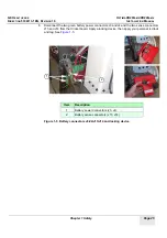
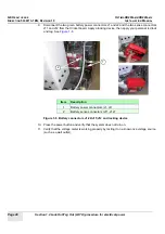
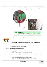
Disconnect the two green battery power connectors J1 and J2 and the two sense connectors
J11 and J12 from the Cricket board. Apply a locking device, then apply your personal red lock
and tag. See
.
Figure 1-6 Battery connectors J1/J2/J11/J12 and locking device
10. Press the power button and verify that the system does not turn on.
11. Verify that the voltage meter is working properly by testing it on a known live voltage source
(such as a wall outlet).
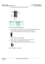
Item
Description
1
Battery power connectors (J1, J2)
2
Battery sense connectors (J11, J12)
1
2
Summary of Contents for Optima XR200amx
Page 129: ......


