GE H
EALTHCARE
O
PTIMA
XR200
AMX
/XR220
AMX
D
IRECTION
5336113-1EN, R
EVISION
10
I
NSTALLATION
M
ANUAL
Chapter 1 Safety
Page 27
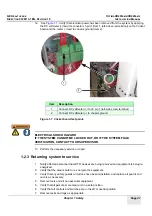
12. See
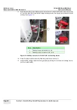
. Verify that electrical power has been removed from the system by applying
the DC voltmeter (+) lead to connector J5 pin 1 (Item 1, left-side screw terminal) on the Cricket
board and the meter (-) lead to chassis ground (Item 2).
Figure 1-7 Cricket board test points
ELECTRICAL SHOCK HAZARD
IF THE SYSTEM CANNOT BE LOCKED OUT, OR IF THE SYSTEM FAILS
VERIFICATION, CONTACT YOUR SUPERVISOR.
13. Perform the necessary service or repair.
1.2.3 Returning system to service
1.
Notify affected personnel that LOTO devices are being removed and equipment is being re-
energized.
2.
Verify that the area is safe to re-energize the equipment.
3.
Verify that any safety guards or devices have been reinstalled, and replace all guards and
covers as necessary.
4.
Remove tools and all non-essential equipment.
5.
Verify that all personnel are clear and in a safe position.
6.
Verify that all controls and switches are in the off or neutral position.
7.
Remove locks and tags as appropriate.
Item
Description
1
Connect DC voltmeter (+) to J5 pin 1 (left-side screw terminal)
2
Connect DC voltmeter (-) to chassis ground
1
2
Summary of Contents for Optima XR200amx
Page 129: ......

