


CHAPTER 13: SERVICING THE D400
D400 SUBSTATION GATEWAY INSTRUCTION MANUAL
GE INFORMATION
165
NOTE
The proper orientation of the LED1/2 connector is for the polarity tab keying feature to
be facing out towards the card edge), and for the LAN1/2 connector polarity tab
keying feature to be facing in from the card edge.
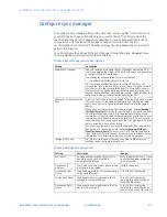
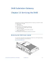
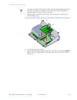
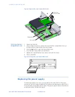
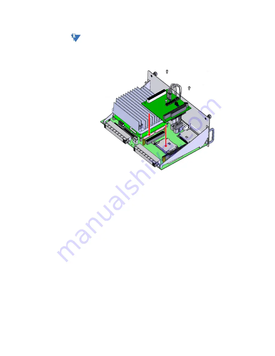
7.
Attach the Ethernet Module card to the expansion slot and secure using the four
provided Philips screws.
Figure 66: Dual Ethernet upgrade kit with card 580-3410 - attach Ethernet module card
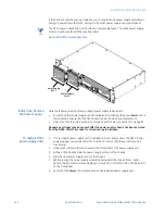
8.
Re-insert the D400 main module.
9.
Power up the D400 and configure the network connections as required using
d400cfg
.
Refer to chapter: “Using the D400 Local Configuration Utility” on page 133 for more
information.
Summary of Contents for Multilin D400
Page 12: ...12 GE INFORMATION D400 SUBSTATION GATEWAY INSTRUCTION MANUAL PRODUCT SUPPORT ...
Page 28: ...28 GE INFORMATION D400 SUBSTATION GATEWAY INSTRUCTION MANUAL CHAPTER 1 BEFORE YOU START ...
Page 34: ...34 GE INFORMATION D400 SUBSTATION GATEWAY INSTRUCTION MANUAL CHAPTER 2 INSTALLING THE D400 ...
Page 88: ...88 GE INFORMATION D400 SUBSTATION GATEWAY INSTRUCTION MANUAL CHAPTER 5 POWERING UP THE D400 ...
Page 174: ...174 GE INFORMATION D400 SUBSTATION GATEWAY INSTRUCTION MANUAL APPENDIX A STANDARDS PROTECTION ...
Page 184: ...184 GE INFORMATION D400 SUBSTATION GATEWAY INSTRUCTION MANUAL APPENDIX C LIST OF ACRONYMS ...
Page 192: ...192 GE INFORMATION D400 SUBSTATION GATEWAY INSTRUCTION MANUAL INDEX ...


