CHAPTER 3: SETTING UP COMMUNICATION CARDS
D400 SUBSTATION GATEWAY INSTRUCTION MANUAL
GE INFORMATION
45
•
Pulse Width Code IRIG-B (
TTL
) through a terminal block
TB1
(TTL) input accepts B00X and B22x, however, the SBS field is decoded but not used to
set the time. The connector used is a 2 position pluggable terminal block, Molex P/N
39530-0002 (GE part number 640-0956)
•
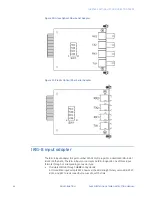
Fiber Optic through a Receive (
RX)
820 to 850 nm ST connector
U12
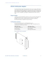
The IRIG-B signal (TTL) can be subsequently distributed to attached devices through one of
the following options:
•
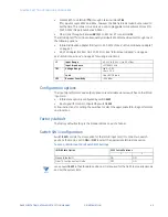
IRIG-B Distribution Adapter (GE Item No. 520-0212LF). See “IRIG-B distribution adapter”
on page 47.
•
RS-232 Adapter (GE Item No. 520-0207LF). See “IRIG-B input adapter” on page 44.
See “IRIG-B connections” on page 63 for wiring instructions.
Configuration options
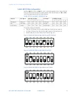
The input signal formats and output options are selectable via two switches on the IRIG-B
Input card:
•
IRIG-B state option is configured by switch
SW1
•
Input signal format is configured by switch
SW2
Follow instructions for setting the switches to select the appropriate IRIG-B signal formats
and functions
.
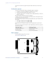
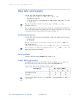
Factory default
The factory default setting is the Standard state on each channel.
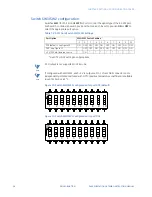
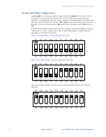
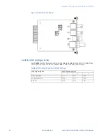
Switch SW1 configuration
Switch
SW1
controls the state option for the IRIG-B Input card. It contains two switch
positions that can be set to
ON
or
OFF
to select the appropriate IRIG-B state option.
Table 11: IRIG-B Input Card Switch SW1 Settings
NOTE
Leave switch
SW1
in the Standard position as it is required for the D400 to properly decode
and set the system time.
J2
Input Range
4.0 V
P-P
to 8.0 V
P-P
; No DC offset
Input Impedance
>1 M
Ω
@ 1 kHz
TB1
Voltage Range
High: > 3.5 V
Low: < 1.5 V
Load
One HCMOS load
U12
Receiver Sensitivity
−
25.4 dBm
IRIG-B State Option
SW1 Switch Positions
1
2
Standard (default)
ON
OFF
Fiber TX Continuous Test Mode
OFF
ON
Summary of Contents for Multilin D400
Page 12: ...12 GE INFORMATION D400 SUBSTATION GATEWAY INSTRUCTION MANUAL PRODUCT SUPPORT ...
Page 28: ...28 GE INFORMATION D400 SUBSTATION GATEWAY INSTRUCTION MANUAL CHAPTER 1 BEFORE YOU START ...
Page 34: ...34 GE INFORMATION D400 SUBSTATION GATEWAY INSTRUCTION MANUAL CHAPTER 2 INSTALLING THE D400 ...
Page 88: ...88 GE INFORMATION D400 SUBSTATION GATEWAY INSTRUCTION MANUAL CHAPTER 5 POWERING UP THE D400 ...
Page 174: ...174 GE INFORMATION D400 SUBSTATION GATEWAY INSTRUCTION MANUAL APPENDIX A STANDARDS PROTECTION ...
Page 184: ...184 GE INFORMATION D400 SUBSTATION GATEWAY INSTRUCTION MANUAL APPENDIX C LIST OF ACRONYMS ...
Page 192: ...192 GE INFORMATION D400 SUBSTATION GATEWAY INSTRUCTION MANUAL INDEX ...

