background image

INSTALLATION REFERENCE CHART

INSTALLATION REFERENCE CHART

Detailed instructions are contained in the Reference Manual, P/N 05-4055A01

INSTALLATION SUMMARY

Step 1 — Initial Checkout

Set the equipment up in a tabletop arrangement.

Review the transceiver

'

s Configuration. As a minimum, Access Points must have the following programmed: IP Address,

IP Network identifier, and Radio Network Address. (RF output power and Password should also be reviewed and set

as necessary.) Remote radios normally re

q

uire only a Radio Network Address to be set. (Note: The Remote Radio

Network Address 

must

 match that of the AP.)

Connect data equipment to the transceivers.
Verify proper exchange of data communications by viewing the LEDs:

PWR

Lit continuously

LINK

Lit continuously

ETH

Lit continuously (unless Sleep is activated)

COM2

Blinking to indicate exchange of data communications

Step 2 — Endpoint Connectivity (PING) Test

for Ethernet Systems Only

Verify the link integrity between the Access Point and endpoint devices connected to Remotes by issuing a 

PING

command from the AP.

Step 3 — Set Configuration of AP and Remote Radios

Step 4 — Install the Equipment in the Field

After basic installation, optimize the performance of the radio network.

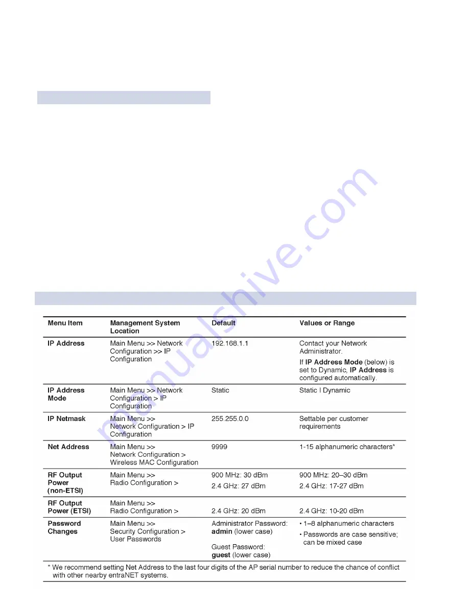
KEY AP PARAMETERS & DEFAULTS

Summary of Contents for MDS entraNET Series

Page 1: ...Start Up Guide Access Point Remote 900 MHz and 2400 MHz Extended Range IP Networking Transceivers Firmware Release 3 0 MDS 05 4565A01 Rev A MAY 2007 MDS entraNET Series...

Page 2: ...Refer to the Installation Reference Chart at the middle of this guide for essential installation and configuration details...

Page 3: ...emote Radio 10 Step 6 Connect the Terminal Equipment 11 Step 7 Check for Normal Operation 12 Resetting to Factory Defaults Use with Care 14 AIMING DIRECTIONAL ANTENNAS FOR MAXIMUM RSSI 15 TROUBLESHOOT...

Page 4: ...ins Installation in Hazardous Locations The transceiver is not acceptable as a stand alone unit for use in hazardous locations It must either be mounted within another piece of equipment which is cert...

Page 5: ...f this equipment About This Guide This guide presents installation and initial operating instructions for the MDS entraNET Series networking transceivers Following installation we suggest keeping this...

Page 6: ...A repeater scheme can be established to extend the transmission range or to work around obstructions in a network This is accomplished by connecting two radios back to back at a single site Industria...

Page 7: ...te www GEmds com INSTALLATION STEPS There are three main requirements for installing the transceiver They are adequate and stable DC power a good antenna system and the correct interface between the t...

Page 8: ...available with an optional 35 mm DIN Rail Mounting Bracket Part No 03 4022A02 Equipment cabinets and racks of recent design often employ this type of mounting A transceiver with a DIN bracket can be q...

Page 9: ...ng a minimum of 11 Watts Typical power consumption is 800 mA at 13 8 Vdc for the AP and 600 mA at 13 8 Vdc for Remotes A power connector with screw terminals is provided with each radio Strip the wire...

Page 10: ...t to the AP using a serial or Ethernet connection Console Terminal Connection recommended for first time log in To configure the AP using the serial COM1 port connect a PC to the COM1 port on the radi...

Page 11: ...hown in Table 2 are the only settings that need to be set or reviewed A complete list of AP commands appears in the MDS entraNET System Guide 05 4055A01 Table 2 Key AP Parameters Defaults Menu Item Ma...

Page 12: ...c characters A good choice is the last four digits of the AP serial number RF Output Power non ETSI Main Menu Radio Configuration 900 MHz 30 dBm 2 4 GHz 27 dBm 900 MHz 20 30 dBm 2 4 GHz 17 27 dBm RF O...

Page 13: ...y to accept com mands c Set or Verify Network Address Type RADIO NETADDR to display the currently programmed network address If changes are required type RADIO NETADDR netaddr where netaddr is 1 15 al...

Page 14: ...t the port settings are compatible with the connected device baud rate data format etc Step 7 Check for Normal Operation In this step you will verify the proper operation of wireless communi cations b...

Page 15: ...lly Alarmed An alarm event has been logged and not cleared At Remote Units a Look for the LINK LED to light and remain on This indicates the unit has successfully associated with the Access Point Asso...

Page 16: ...work is operating properly based on observation of the unit s LEDs connect a computer to the transceiver s data port that will be used by the local terminal equipment Send the PING command to verify t...

Page 17: ...ole Baud Rate Device Names Radio Packet Statistics Ethernet Wireless Packet Statistics DNP3 Routing DNP Multicast Address DNP Multicast Port DNP Unicast Port DNP Routing Enable DNP Routing Database Re...

Page 18: ...s to be set Note The Remote Radio Network Address must match that of the AP Connect data equipment to the transceivers Verify proper exchange of data communications by viewing the LEDs PWR Lit continu...

Page 19: ...in a large part on stable radio signal levels being received at each end of a data link In general signal levels stronger than 90 dBm provides the basis for reliable communication that includes a 15...

Page 20: ...o Packet Statistics Screen Figure 8 on Page 24 This information will be used later 3 Clear the Radio Statistics history 4 Read the RSSI level at the Remote RADIO RSSI 5 Optimize the RSSI by slowly adj...

Page 21: ...e Remotes radios to be connected must operating properly so data layer traffic can function Radio Configuration There are over 50 parameters in the entraNET MS With so many set tings a parameter may b...

Page 22: ...ient condition Cycle the power and wait about 30 seconds for the radio to restart Recheck for normal operation LINK LED does not turn on a The Remote network address does not match the desired AP Veri...

Page 23: ...t through or crossover is used See Table 5 below for the proper cable type COM1 or COM2 LED does not show traffic Check the configuration of COM port and the remote serial gateway settings Table 5 Pro...

Page 24: ...esolution Remotedoesnot associate a Verify that the AP has a sufficiently large number in the Max Remotes parameter of the Network Configuration Menu b If Approved Remotes is enabled on the Security C...

Page 25: ...for secure cable connections Serial data cable should be as short as possible never exceeding 50 feet 15 meters b Connect to the AP menu and manage the Remote via the Serial Configuration menu Check...

Page 26: ...antennas This often limits interference to and from other stations b Try skipping some zones where persistent interference is suspected or packets per zone are disparate c The installation of a filte...

Page 27: ...between the radio being viewed and the network through the network layer These include Wireless Packet Statistics Packets received Packets dropped Packets sent Receive errors Bytes received Retries B...

Page 28: ...er When troubleshooting throughput quality issues a check should also be made of the Radio Packet Statistics Screen shown in Figure 8 This menu provides a review of packet statistics from a radio link...

Page 29: ...ay eliminate or reduce harmful interference Serial Port and Remote Serial Statistics Menu Figure 9 Serial Data Statistics Screen This screen provides top level information on data exchanges between th...

Page 30: ...online at www GEmds com support product sro Your number will be issued immediately after the required information is entered Please be sure to have the model number s serial number s detailed reason f...

Page 31: ...Installation Guide...

Page 32: ...GE MDS LLC Rochester NY 14620 General Business 1 585 242 9600 FAX 1 585 242 9620 Web www GEmds com 175 Science Parkway...

Reviews: