3-
4
DGP Digital Generator Protection System
GE Power Management
3.2 CIRCUIT BOARD MODULES
3 HARDWARE DESCRIPTION
3
3.2 CIRCUIT BOARD MODULES
3.2.1 WARNING
This relay contains electronic components that could be damaged by electrostatic discharge
currents. The main source of electrostatic discharge currents is the human body, and the con-
ditions of low humidity, carpeted floors, and isolating shoes are conducive to the generation
of electrostatic discharge currents. Where these conditions exist, care must be exercised
when removing and/or handling the modules. The persons handling the modules must ensure
that their body charge has been discharged by touching some surface at ground potential
before touching any of the components on the modules.
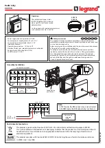
3.2.2 BASIC CONSTRUCTION
Each module consists of a printed-circuit board and front panel. Two knobs are provided on the front panel for
removing and inserting the module. Electrical connection is made by the 96 pins of the Eurocard connector
located at the back of the board.
3.2.3 IDENTIFICATION
Each module has its own identification number, consisting of a three-letter code followed by a three-digit num-
ber. These are found at the bottom of each front panel.
Figure 3–3: DGP POWER SUPPLY MODULE
CAUTION
Summary of Contents for DGP Series
Page 2: ......
Page 4: ......
Page 192: ...8 18 DGP Digital Generator Protection System GE Power Management 8 5 PASSWORDS 8 INTERFACE 8...
Page 260: ...B 4 DGP Digital Generator Protection System GE Power Management B 1 CHANGE NOTES APPENDIXB B...
Page 262: ...B 6 DGP Digital Generator Protection System GE Power Management B 1 CHANGE NOTES APPENDIXB B...
Page 268: ...D 2 DGP Digital Generator Protection System GE Power Management D 1 DGP WARRANTY APPENDIXD D...
Page 276: ...viii DGP Digital Generator Protection System GE Power Management INDEX INDEX...
Page 277: ...GE Power Management DGP Digital Generator Protection System NOTES...