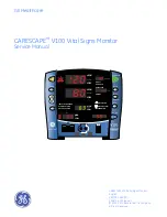
GE CareScape V100 Service Manual Download Page 1

GE Healthcare

CARESCAPE

 V100 Vital Signs Monitor

Service Manual

HISTORY

AUTO CYCLE

MAP/Cuff

BATTERY OK

BATTERY LOW
CHARGING

Pulse Rate

Temperature

SpO

Silence

Alarms

Menu

Cycle

History

To clear hold 

2 seconds

On / Off

Print

C
F

Inflate/Stop

HIGH

HIGH

LOW

LOW

Diastolic

Systolic

HIGH
LOW

HIGH
LOW

ALARM VOLUME

PULSE VOLUME

INFLATE PRESSURE

NEONATE

ADULT

CARESCAPE V100 Vital Signs Monitor
English
2037107-002 (CD)
2048724-002 (paper)
© 2010, 2011 General Electric Company.
All rights reserved.

Summary of Contents for CareScape V100

Page 1: ...ature S pO Silence Alarms Menu Cycle History To clear hold 2 seconds On Off Print C F Inflate Stop HIGH HIGH LOW LOW Dias tolic S ys tolic HIGH LOW HIGH LOW ALARM VOLUME PULSE VOLUME INFLATE PRESSURE NEONATE ADULT CARESCAPE V100 Vital Signs Monitor English 2037107 002 CD 2048724 002 paper 2010 2011 General Electric Company All rights reserved ...

Page 2: ...ral Electric Corporation All other product and company names are the property of their respective owners CARESCAPE CRITIKON DINALINK DINAMAP DURA CUF and SOFT CUF Blood Pressure Cuffs and SuperSTAT are trademarks of GE Medical Systems Information Technologies Inc Turbo TempTM Alaris Tri Site and IVAC are trademarks of CareFusion Corporation Exergen and TAT 5000 are trademarks of Exergen Corporatio...

Page 3: ... 4 Responsibility of the manufacturer 1 4 General 1 4 Dangers warnings cautions and notes 1 5 Product specific hazards 1 5 Equipment symbols 1 10 Service requirements 1 13 Equipment ID 1 13 Related manuals 1 14 Service policy 1 14 Service contracts 1 14 Assistance 1 14 Service 1 14 Packing instructions 1 15 Insurance 1 15 Repair parts 1 15 Disposal of product waste 1 15 Batteries 1 16 Patient appl...

Page 4: ...ssure NIBP and pulse 2 8 DINAMAP SuperSTAT algorithm 2 9 DINAMAP Classic and auscultatory reference algorithm 2 11 Reference used to determine NIBP accuracy 2 12 Temperature 2 13 Alaris temperatures 2 13 Exergen temperature 2 14 Functional description 2 14 Main board PWA 2 14 User interface UI board PWA 2 15 SpO2 PWA 2 15 Printer 2 16 Pneumatics 2 16 Optical switch 2 16 3 Installation 3 1 Unpackin...

Page 5: ...3 16 Communication protocol 3 16 4 Maintenance 4 1 Preventative maintenance 4 2 Maintenance schedule 4 2 Integrity of hoses and cuffs 4 2 Visual inspection 4 3 Cleaning 4 3 Cleaning schedule 4 3 Cleaning the monitor monitor accessories and the Exergen temporal scanner 4 3 Cleaning and disinfecting blood pressure cuffs 4 5 Cleaning the exterior surfaces of the Alaris temperature devices 4 6 SpO2 se...

Page 6: ...cation 4 19 Alaris temperature probe date of manufacture 4 20 Exergen temperature calibration verification 4 20 SpO2 perform only if equipped with SpO2 module 4 21 Printer output test 4 22 Safety testing 4 23 Electrical safety tests 4 23 Recommendations 4 23 Test equipment 4 24 Power outlet test 4 24 Power cord and plug 4 24 Patient leakage current test 4 25 Patient leakage current test mains volt...

Page 7: ...essories 6 14 Connectivity accessories 6 14 Field replaceable units FRUs 6 15 FRU list 6 15 FRU photos 6 17 FRU main reference guide drawing 6 28 Disassembly reassembly of FRUs 6 36 Electrostatic discharge ESD precautions 6 36 Monitor fascia replacement procedure 6 37 Monitor disassembly procedure 6 39 Main battery 6 39 Rear case 6 40 Printer 6 41 SpO2 board 6 42 Front bezel 6 42 Main board 6 43 D...

Page 8: ...ergen A 18 B Appropriate use of NIBP simulators B 1 Appropriate use of NIBP simulators B 2 NIBP accuracy B 2 Clinical vs simulator readings B 2 What do simulator manufacturers say B 3 Why use simulators B 4 Summary B 4 C Electromagnetic compatibility EMC C 1 Electromagnetic compatibility EMC CARESCAPE V100 monitor C 1 Guidance and manufacturer s declaration electromagnetic emissions C 1 Guidance a...

Page 9: ...2048723 002C CARESCAPE V100 Vital Signs Monitor 1 1 1 Introduction ...

Page 10: ...l so they can maintain the equipment to the assembly level Use it as a guide for maintenance and electrical repairs considered field repairable Where necessary the manual identifies additional sources of relevant information and technical assistance See the operator s manual for the instructions necessary to operate the equipment safely in accordance with its function and intended use Intended aud...

Page 11: ...ion names are enclosed in double quotes Maintenance The word select means choosing and confirming Messages alarm messages informative messages displayed on the screen are written inside single quotes Learning Note statements provide application tips or other useful information All illustrations in this manual are provided as examples only They may not necessarily reflect your monitoring setup or d...

Page 12: ...for home use Federal law U S A restricts this device to be sold by or on the order of a physician Contact GE for information before connecting any devices to the equipment that are not recommended in this manual Parts and accessories used must meet the requirements of the applicable IEC EN 60601 series safety standards and or the system configuration must meet the requirements of the IEC 60601 1 1...

Page 13: ...CAUTION indicates a hazardous situation that if not avoided could result in minor or moderate injury NOTE provides application tips or other useful information to assure that you get the most from your equipment Product specific hazards DANGER Do not service the battery while the monitor is connected to external power WARNING Do not immerse the monitor in water If the monitor is splashed with wate...

Page 14: ...nverter use only GE approved power adapters and converters WARNING The speaker is tested during unit power up If the power up tones are not heard audible alarms will also not be heard WARNING If the Power On Self Test fails do not use the monitor WARNING Inspect the device for damage prior to use WARNING Do not disassemble modify or destroy the battery Doing so can cause battery fluid leakage heat...

Page 15: ...internal charger and may cause battery acid leakage fire or explosion WARNING The battery will completely discharge if the monitor is stored for a prolonged period of time with the battery left inside and not periodically recharged Configuration settings may be lost as a result WARNING Charge the battery pack with the monitor s internal charger only Use of an unrecommended charger may cause batter...

Page 16: ...titution using this equipment to implement a satisfactory maintenance schedule may cause undue equipment failure and possible health hazards WARNING The use of accessories transducers and cables other than those specified may result in increased emissions and or increased susceptibility to electromagnetic interference This may result in impaired operation of the monitor and or devices in the area ...

Page 17: ...n Replacement batteries are available from GE CAUTION The monitor is designed to conform to Electromagnetic Compatibility EMC standard IEC 60601 1 2 and will operate accurately in conjunction with other medical equipment which also meets this requirement To avoid interference problems affecting the monitor do not use the monitor in the presence of equipment which does not conform to these specific...

Page 18: ...l equipment requires special electromagnetic compatibility EMC precautions which must be considered when installing and putting this equipment into operation For detailed information refer to the Electromagnetic compatibility EMC appendix in this manual Equipment symbols The following symbols are associated with the CARESCAPE V100 vital signs monitor NOTE The model of the monitor determines which ...

Page 19: ...quipment European authorized representative External communications port connector External DC power input Fragile Handle with care Humidity limitations Ordinary Equipment Exergen only This product is protected against vertically falling drops of water and conforms with the IEC 60529 standard at level of IPX1 No harmful effects will come of vertically falling drops of water making contact with the...

Page 20: ...liance and Materials is a mandatory mark required on Electrical Appliances in Japan as authorized by the Electrical Appliance and Material Safety Law DENAN This mark signifies that a product complies with the law according to a set of standards for electric devices Temperature limitations WASTE OF ELECTRICAL AND ELECTRONIC EQUIPMENT WEEE This symbol indicates that the waste of electrical and elect...

Page 21: ...ng this equipment to implement a satisfactory maintenance schedule may cause undue equipment failure and possible health hazards Regular maintenance irrespective of usage is essential to ensure that the equipment will always be functional when required Equipment ID Every GE device has a unique serial number for identification A sample of the information found on a serial number label is shown belo...

Page 22: ...le to resolve the problem after checking these items contact GE Prior to calling please be prepared to provide product name model number and serial number a complete description of the problem If repair parts or service are necessary you will also be asked to provide the facility s complete name address and account number a purchase order number if the product needs repair or when you order spare ...

Page 23: ...riginal shipping carton is not available Place the product in a plastic bag and tie or tape the bag to prevent loose particles or materials from entering openings such as hose ports Use a sturdy corrugated container to ship the product tape securely to seal the container for shipping Pack with at least 4 inches of padding on all sides of the product Insurance Insurance is at the customer s discret...

Page 24: ...nd should be disposed of properly as medical waste in accordance with regional body controlled guideline Other patient applied parts such as blood pressure cuffs should be cleaned according to instructions Inspect reusable applied parts for wear replace as necessary and dispose of used product as medical waste in accordance with regional body controlled guideline Packaging material Retain original...

Page 25: ...2048723 002C CARESCAPE V100 Vital Signs Monitor 2 1 2 Equipment overview ...

Page 26: ... signs monitor determines which parameters are in your monitor Please refer to applicable sections Using the CARESCAPE V100 vital signs monitor a clinician can measure display and record patient vital sign data that is derived from each parameter The monitor is also capable of alerting the clinician to changes in the patient s condition or when it is unable to effectively monitor the patient s con...

Page 27: ...and history When you are in limit or menu setting pressing the button increases and decreases an adjustable setting When you are in cycle or history mode pressing the buttons displays the next or previous cycle selection or entry in the history list respectively When you reach the beginning or ending of a list a negative key click sounds 4 Menu button accesses menu settings that can be adjusted IN...

Page 28: ... 6 Front panel indicators 15 Alarm silence indicator Solid red Indicates that an alarm silence is active and the audible alarm tones are silenced for 2 minutes Blinking red Legacy alarm mode only Indicates that an alarm silence is not active and at least one alarm condition is present 16 Systolic window indicates measured systolic NIBP in mmHg 17 Diastolic window indicates measured diastolic NIBP ...

Page 29: ... limits or inflation pressure settings 27 AUTO CYCLE indicator lights green to indicate auto mode is the chosen NIBP mode flashes to indicate you are making a change to the auto mode 28 Min window displays the NIBP mode if manual or Stat as well as the cycle time when taking auto NIBP determinations 29 HISTORY indicator flashes to indicate you are in history mode 30 BATTERY OK indicator lights gre...

Page 30: ...ns monitor with other electronic devices a central nurse s station or remote alarm device or with the Exergen scanner For further information reference the Host Communication manual CARESCAPE V100 vital signs monitor connectivity options The following connectivity options are available for use with the CARESCAPE V100 vital signs monitor and can be purchased from GE DINALINK adapter The DINALINK ad...

Page 31: ...r use in the presence of an oxygen enriched atmosphere oxygen tent Type BF defibrillation proof applied parts IPX1 degree of protection against ingress of water Sterilization Disinfection see Cleaning on page 4 3 Software is developed in accordance with IEC 60601 1 4 The monitor complies to IEC 60601 2 49 The alarm system is developed in accordance with IEC 60601 1 8 This equipment is suitable for...

Page 32: ...saturation The analog signals are routed to the SpO2 Printed Wiring Assemblies PWA for Ohmeda Nellcor or Masimo The analog signals are analyzed on the SpO2 PWA The results are digitized and sent to the Main Board via opto couplers The couplers provide patient isolation as well as serial data interface The Main Board temporarily stores the data and routes it to the UI Board for display and or print...

Page 33: ...may be necessary to complete the determination process In auto mode the data is stored for up to 16 minutes When employing fewer pressure steps the system uses the stored information from the previous blood pressure determination to decide the best pressure steps to take The algorithm measures the consistency of pulse size to tell if the oscillations taken at a step are good and if more steps are ...

Page 34: ...e screen The operating cycle is composed of four parts inflation time deflation time evaluation time and wait time Wait time which varies from mode to mode is affected by the cycle time auto mode or operator intervention manual mode The figure shows the basic operating cycle for an NIBP determination SuperSTAT NIBP auto mode Systolic search If systolic pressure is not found the SuperSTAT algorithm...

Page 35: ...he oscillometric method of determining NIBP is accomplished by a sensitive transducer which measures cuff pressure and minute pressure oscillations within the cuff The first determination sequence initially pumps up to a cuff pressure of about 160 mmHg for adult pediatric patients or 110 mmHg for neonates depending on initial target pressure preset After inflating the cuff the monitor begins to de...

Page 36: ...mal deflation sequence detect the absence of a systolic value stop deflation reinflate to a higher than initial inflation pressure and resume normal deflation sequence In manual mode if a previous valid systolic pressure is displayed and less than 2 minutes old and the new systolic pressure oscillations are compared with the previous valid determination and the monitor thinks that the systolic was...

Page 37: ...es the digital signal and displays the patient temperature on the UI Board and printer in Celsius or Fahrenheit When the monitor is powered on the monitor automatically calibrates the temperature circuit to account for ambient room temperature This is done by measuring a high precision resistor of known value computing a calibration factor and applying this factor to all subsequent measurements NO...

Page 38: ...nual for complete instructions for use For more information on the theory of operation scientific educational and technical information access the following website www TAThermometry org Functional description The following paragraphs provide the functional interface relationship The monitor contains a number of electrical and electro mechanical assemblies These assemblies are Main Board PWA User ...

Page 39: ...ser interface UI board PWA The UI Board is used as a message center It displays patient vital signs alarms status monitor set up limit violation NIBP cycle and the time the data was received The primary processor on the Main Board controls the UI Board When the primary processor reads the parameter signals it decodes the signals and routes the display information to the UI Board The UI assembly al...

Page 40: ...printer to print a graphic hardcopy of the patient vital sign values and trend data It also causes the printer to print a hardcopy of error logging and service record data The printer has a built in sensor to monitor the printer paper presence When the printer is out of paper it sends a PAPER OUT signal to the primary processor Pneumatics The pneumatics consists of a pump a deflate valve and a dum...

Page 41: ... Interface Main Board Optical Switch Printer Driver Control Data Speaker Printer Isolated DC Power Supply Host Comm Port rear Control Data RS 232 Remote Alarm Display LEDs Temp Probe optional Temp Control Data Temp Control PT1 PT2 NIBP Data BP Cuff Pump Valve Manifold Tubing Tubing Control SpO2 Probe optional SpO2 Circuit External DC 6V Battery ...

Page 42: ...2 18 CARESCAPE V100 Vital Signs Monitor 2048723 002C Equipment overview Functional description For your notes ...

Page 43: ...2048723 002C CARESCAPE V100 Vital Signs Monitor 3 1 3 Installation ...

Page 44: ... the monitor Power sources The monitor is designed to operate from an internal lead acid main battery NOTE The monitor is not designed to operate without a functional internal main battery Main battery charging Prior to each use inspect the power supply cord to ensure proper connection and condition NOTE Repeated failure to fully recharge the battery will over time lead to a significant reduction ...

Page 45: ... wait until battery is fully discharged To prolong the life of the battery keep the monitor connected to a DC power supply whenever possible Do not allow the battery to become completely discharged A fully charged battery will power the monitor for approximately 5 11 hours depending upon configuration and usage To ensure full charge cycles replace only with the specified battery BATTERY OK When th...

Page 46: ...r flashes The monitor alarms for 2 5 minutes then shuts down completely NOTE You must plug the monitor into DC power before resuming monitoring After plugging the monitor into DC power The BATTERY LOW indicator when the monitor is on and CHARGING indicator illuminate The BATTERY LOW indicator turns off when the battery level reaches a sufficient charge level to operate without the BATTERY LOW alar...

Page 47: ...ain alarm and parameter settings the changes must be done in the configuration mode Date Time settings are also entered in the configuration mode To enter the configuration mode with the monitor off press and hold the Menu button at the same time as pressing and holding the On Off button for 3 seconds The monitor enters the configuration mode For a few seconds immediately after power up in this mo...

Page 48: ...O2 settings are different depending upon the SpO2 technology your monitor contains The Menu selections appear in the following order Refer to the manual section for settings options Display Window Major software revision Systolic Minor software revision Diastolic Type of NIBP technology min Temperature type technology Temperature Setting Window LED display Pulse Rate window display Comment Inflate...

Page 49: ...he Systolic window To change parameter settings press the Menu button SpO2 sat Masimo only SpO2 0 or 1 Fast Sat Mode 0 Off 1 On SpO2 sensitivity Masimo only SpO2 1 2 3 1 Low Perfusion Maximized 2 Low Perfusion Default 3 for engaging Adaptive Probe Off Technology algorithm Temperature units Temperature blank C or F indicator illuminated Alaris only Temperature display time Temperature 2 or 5 User s...

Page 50: ...alarm setting Use the buttons to increment or decrement the individual settings NOTE For the Alarms default setting to be saved you must advance the menu through the SpO2 settings 3 To exit the configuration mode turn the unit off To continue with additional configuration settings press Menu Reverting to the factory default vital sign alarm limits WARNING The Line Frequency mode for Datex Ohmeda o...

Page 51: ...ult settings If the LF mode is set incorrectly the susceptibility to ambient light is increased and low perfusion performance may be affected resulting in potentially inaccurate readings Procedure for units with Nellcor technology 1 With the monitor off press and hold the Menu button at the same time as pressing the On Off button until the display test completes 2 Press the Menu button until n0d r...

Page 52: ...e same time as pressing the On Off button until the display test completes 2 Press the Menu button until Unt unit of measurement appears in the Pulse Rate window 3 Use the buttons to select the option 4 To exit the configuration mode turn the unit off To continue with additional configuration settings press the Menu button Procedure for units with Exergen scanner The Exergen scanner comes preset w...

Page 53: ...lect the option 4 To exit the configuration mode turn the unit off To continue with additional configuration settings press the Menu button Advanced configuration mode Advanced Configuration mode is entered by holding the Menu button and the button simultaneously while powering on with the On Off button For a few seconds immediately after power up in this mode the Systolic and Diastolic display wi...

Page 54: ...cer calibration pages are available until calibration is valid Save settings Calibration and other service mode setting changes will not be retained unless the Save Settings operation is executed on the final Service Mode options page To save settings in service mode advance to the last page page 6 then press and hold the Menu button until the second of two tones sound Displayed on monitor Functio...

Page 55: ...ration section for functions 2 in min window Refer to calibration section for functions 3 in min window NIBP Algorithm Type loaded Displayed in MAP Cuff display window 1 DINAMAP Classic NIBP 2 DINAMAP Auscultatory NIBP 3 DINAMAP SuperSTAT NIBP NOTE Changing setting effects NIBP performance 3 in min window Alarm mode Displayed in Pulse Rate window 0 IEC mode 1 Legacy mode NOTE Use the Alarms button...

Page 56: ... min window Language The number displayed in Pulse Rate display window indicates the language setting These range from 0 to 20 For example 0 indicates English The language setting is used in printed reports Russian Greek Korean and Japanese are printed in English only 0 English 1 Not used 2 Czech 3 Danish 4 Dutch 5 Finnish 6 French 7 German 8 Greek 9 Hungarian 10 Italian 11 Japanese 12 Korean 13 N...

Page 57: ...26 along with the Host Comm Cable Assemblies GE part numbers 683235 and 683242 USB Cable Kit GE part number 2040229 001 If external alarm control is required the Isolated Remote Alarm Cable GE part number 487208CR should always be used When a high priority alarm condition is displayed on the monitor the remote alarm signal becomes active within 0 5 seconds The active state of the alarm signal is a...

Page 58: ...ange data with the monitor including the Host Communications Reference Manual and the DINAWIN Application Programming Interface library Contact your GE sales representative for further information Pin Function 1 Common 2 Inverted TTL Transmit Data 3 Inverted TTL Receive Data 4 5 volts 5 No connection 6 No connection 7 Common 8 Remote Alarm 9 No connection 10 No connection 11 RS232 Transmit Data Tx...

Page 59: ...2048723 002C CARESCAPE V100 Vital Signs Monitor 4 1 4 Maintenance ...

Page 60: ...als hospitals or institutions utilizing the device Maintenance schedule To ensure the monitor and its components remain in proper operational and functional order the following maintenance schedule is recommended Visual inspection Prior to installation every 12 months thereafter and each time the equipment is serviced Parameter level functional testing After the initial configuration is complete C...

Page 61: ...ect the display face for marks scratches or other damage Safety labels and inscription on the device are clearly legible Cleaning Cleaning schedule CAUTION To prevent cross contamination clean the exterior surfaces of the monitor monitor accessories and reusable sensors on a regular basis in compliance with your institution s infection control unit and or biomedical department s local policy Clean...

Page 62: ...ver an alcohol based cleaning agent can be used on the Exergen scanner s probe head and metal neck only Petroleum based cleaning agents Any type of solution that contains ammonium chloride conductive solutions wax or wax compounds Sodium salts NOTE Never autoclave or steam clean the monitor cuffs or accessories Cleaning the displays of the monitor or Exergen temporal scanner To clean the display c...

Page 63: ... the enzymatic detergent according to the manufacturer s instructions and the 10 bleach solution in separate spray bottles 2 Spray the detergent liberally on the cuff If the material is dried on allow the detergent to set for 1 minute For soil on the soft part of the closure or the cuff itself wipe the material off with a soft cloth For persistent contamination on the soft part of the closure use ...

Page 64: ...ice or distributor Do not use alcohol ammonia or ammonium chloride based agents as they could damage the plastic exterior of the probe Do not allow fluids to enter the probe Fluid leakage into the probe can cause damage Do not autoclave or immerse the probe as damage will occur SpO2 sensors Adhesive sensors are sterile and for single use only For reusable temperature sensors consult the sensor man...

Page 65: ...n 6 months without a full recharge A fully charged battery in good condition will provide sufficient power to operate a monitor for approximately 5 11 hours depending upon configuration and use With the usage scenario of auto NIBP every 5 minutes with adult cuff printout after every determination SpO2 parameter active at 60 bpm temperature parameter active in monitor mode the average run time is 5...

Page 66: ...Unplug the monitor from the DC power source 2 Looking at the bottom of the monitor remove the battery compartment cover by removing the four screws that secure the cover and help card tray 3 Remove the help card tray and battery door cover WARNING When reconnecting the battery ensure the battery maintains the correct polarity by connecting the red lead to the positive terminal and the black lead t...

Page 67: ...ogy it is important to verify the Line Frequency mode setting Configured settings and time date will not be lost when reset due to pressing and holding the On Off button regardless of whether the DC charger is attached 8 Reset the date time and applicable user settings 9 Verify the configuration settings prior to returning the monitor to clinical use Exergen temporal scanner battery NOTE If the Ex...

Page 68: ...y in the same location 4 Replace the battery cover and tighten the screw 5 Reconnect the scanner cable to the host communication port and tighten the two thumbscrews Fuses The monitor contains three fuses The fuses are mounted within the monitor The fuses protect the low voltage DC input the main battery and the remote alarm output The 5 V output on the host port connector is regulated by internal...

Page 69: ...Verify that a blood pressure determination completes and the results are displayed on the monitor NOTE While an NIBP simulator device may be useful to verify that the monitor responds to oscillometric pulsations it should not be used as a basis for assessing the accuracy of measurement For more information see Appropriate use of NIBP simulators on page B 2 Temperature Alaris NOTES Predictive tempe...

Page 70: ...i e not on a resistor simulator 3 Verify that the temperature displays both on the Exergen temporal scanner and in the Temperature window on the monitor Ohmeda Nellcor and Masimo SpO2 technologies The SpO2 sensor is an assembly consisting of two parts the sensor and the extender cable 1 Connect the cables prior to attaching to the monitor 2 Verify that an SpO2 reading is displayed within moments o...

Page 71: ... type if SpO2 is installed TE 1811 Temperature Probe Simulator if TEMP is installed available from CareFusion Corporation Exergen Calibration Verification Kit if Exergen option is installed p n EX129003 Printer paper if printer is installed 3 diameter rigid cylinder mandrel SpO2 connector with all leads shorted Temperature connector with all leads shorted DC input connector with both wires shorted...

Page 72: ...NOTE To enter Service Mode press and hold the Cycle button while pressing the On Off button 1 Turn unit on and enter Service Mode 2 Press Cycle button and 1 should appear in the min window 3 Close the valve on the inflation bulb 4 Using the inflation bulb inflate the system to 210 mmHg 5 Allow the system to stabilize for 5 seconds it is normal to see some decrease in pressure at this point 6 Start...

Page 73: ...setup to 200 mmHg 6 Record and verify the pressure reading that appears in the Systolic window 7 Record and verify the pressure reading that appears in the Diastolic window 8 Use the valve on the bulb to reduce pressure to 150 mmHg 9 Record and verify the pressure reading that appears in the Systolic window 10 Record and verify the pressure reading that appears in the Diastolic window 11 Use the v...

Page 74: ...ation setting press the Cycle button until 6 appears in the min window 9 Press and hold Menu button until monitor beeps and the number in the MAP Cuff window decrements by 1 which acknowledges that data was saved 10 Turn the monitor off Overpressure verification NOTE To enter service mode press and hold Cycle button while pressing the On Off button 1 Wait a few seconds after entering service mode ...

Page 75: ...NIBP simulators on page B 2 1 Remove the calibration setup and attach an adult cuff and hose to a simulator be sure to select the correct cuff size 2 Press Inflate Stop button on monitor to begin a determination 3 Record Systolic Diastolic MAP and heart rate from the monitor display 4 Wait 1 minute then press Cycle button to initiate a determination in Auto NIBP mode 5 Record Systolic Diastolic MA...

Page 76: ...llowing figure the items with a solid border are segment LEDs and the items with a dotted border are discrete LEDs 3 Repeat power up cycle until all LEDs are checked 4 Confirm all test results are recorded on the Test results form on page 4 29 External DC verification 1 Plug the power supply into the monitor 2 Verify that the CHARGING indicator is illuminated 3 Confirm all test results are recorde...

Page 77: ...ent units to F Refer to Temperature unit of measurement configuration settings on page 3 10 for instructions 6 Put the monitor into temperature monitor mode a Remove the probe from the well b Press the key c Verify that a blinking temperature appears quickly If not return the probe to the holder and repeat steps 6a and 6b 7 Record and verify the reading in the temperature display is 80 2 F 0 2 F 8...

Page 78: ...e recalibration If readings are not correct the instrument should be returned for repair NOTE If calibration is needed return the unit to the manufacturer Calibration verification kit The calibration verification procedure requires the Exergen Calibration Verification Kit p n EX129003 The calibration verification kit includes a portable blackbody heat generator providing a stable source of heat in...

Page 79: ...ce instrument and the instrument being verified into the aperture opening comparing the readings 6 Record and verify the difference between the temperature reading of the CM and the instrument being verified is 0 2 C 0 4 F If the readings differ by more than the acceptable field limits repeat this procedure If the readings still differ by more than the acceptable limits the device fails 7 Confirm ...

Page 80: ...st results form on page 4 29 Printer output test 1 Load paper into the print mechanism NOTE Use only printer paper from GE a With the monitor powered on turn it so that the side with the printer is facing you b While grasping the side of the monitor lift the printer door open by placing your thumb in the indented area and pulling The printer door will pop open c Place the roll of paper into the co...

Page 81: ...mendations Qualified personnel must perform all safety tests presented in this document Upon receipt of the monitor and its associated equipment Every 12 months thereafter Planned Preventive Maintenance Refer to the Maintenance schedule on page 4 2 for more information Each time the main enclosure is disassembled or a circuit board is removed tested repaired or replaced Corrective Maintenance GE r...

Page 82: ...cord and plug Verify the power cord being used with the patient monitor is good The following are several areas to check for in this regard Failure of the power cord strain relief is very common Often times users of the equipment pull on the power cord itself rather than the power cord plug to unplug the patient monitor from a wall receptacle Inspect the power cord for wear or damage regularly If ...

Page 83: ...test body shorts all signals in the connector together Refer to the instructions contained with the safety analyzer to perform this test NOTES Perform this test once for SpO2 and once for Temperature This test applies only to the Alaris temperature option it is not intended for the Exergen temperature option 1 Connect the appropriate Test Body to the input connector of the device under test 2 Conf...

Page 84: ...VERSED Neutral OPEN GND Earth CLOSED 12 Read the current leakage indicated on the tester and record the results on the Test results form on page 4 29 13 Change leakage tester switches to Polarity REVERSED Neutral CLOSED GND Earth CLOSED 14 Read the current leakage indicated on the tester and record the results on the Test results form on page 4 29 15 Remove the AC mains voltage from the device und...

Page 85: ...aracteristics per IEC 60601 1 Per IEC 60601 1 the resistance to protect the circuitry and the person performing the test The resistance must be low enough to accept currents higher than the allowable values of the leakage current to be measured WARNING Shock hazard The following step causes high voltage at the test body Do not touch the test body NOTE Perform this test once for SpO2 and once for T...

Page 86: ...the results on the Test results form on page 4 29 6 Remove the AC mains voltage from the device under test 7 Repeat the steps in this procedure using the appropriate Test Body for any additional patient connectors requiring safety testing If measured reading is greater than the acceptance criteria below the device under test fails Contact GE Technical Support Acceptance criteria All readings must ...

Page 87: ...eading at 100mmHg bottom display Diastolic 97 103 Pressure reading at 50mmHg top display Systolic 47 53 Pressure reading at 50mmHg bottom display Diastolic 47 53 Overpressure verification Overpressure threshold Adult mmHg 305 325 Overpressure threshold Neonate mmHg 150 165 Buttons NIBP Determination Initiated E80 displayed on Systolic display Audible alarm can be silenced Alarm silence indicator b...

Page 88: ...ding at 107 8 F 107 5 F 108 1 F Exergen Temperature reading of reference instrument Temperature reading of instrument being verified Difference between temperature reading of reference instrument and instrument being verified 0 2 C 0 4 F SpO2 Pulse Value Displayed Saturation Value Displayed Signal Strength Bar displayed on SpO2 display Alarm is silenced error display remains Pulse Value Saturation...

Page 89: ...4 31 Maintenance Test results form Rev Pol Neut Open Gnd Clsd 500µA Rev Pol Neut Clsd Gnd Clsd 100µA Patient leakage current mains on applied part Fwd Pol Neut Clsd Gnd Clsd 5mA Rev Pol Neut Clsd Gnd Clsd 5mA Description Min Max Actual Pass Fail N A ...

Page 90: ...4 32 CARESCAPE V100 Vital Signs Monitor 2048723 002C Maintenance Test results form ...

Page 91: ...2048723 002C CARESCAPE V100 Vital Signs Monitor 5 1 5 Troubleshooting ...

Page 92: ... detailed troubleshooting complete a thorough visual inspection of the following All cable connections secure Devices properly powered Connected to a proper power source Problem Possible reason Solution Exergen temperature does not appear on the monitor The host communication bit rate may be set incorrectly Confirm that the host communication bit rate br is set at the default setting 9600 Refer to...

Page 93: ...onditions and error codes When responding to a monitor alarm always check the patient first and then check the monitor cuff hose and sensors Press Silence to clear patient alarm conditions Error log You can view and print an error log that stores up to 40 error code entries The log is a rolling list that once 40 entries are stored deletes the oldest entry in order to add the most recent entry The ...

Page 94: ...tus from module for 60 10 sec Fatal error reported by module No Verify SpO2 configuration is correct type Parameter turned on no hardware installed in unit 940 Temp TEMP data samples less than 45 in 5 sec while idle No Mains PWA issue 950 NIBP NIBP pump on during idle or over current detected No Pneumatic assembly failure 951 NIBP NIBP valve stuck closed during cuff typing No Pneumatic assembly fa...

Page 95: ...es No paper in printer Printer problem E11 Printer Printer too hot Yes Printer problem E13 Battery Main battery low Yes Battery too low to operate the unit Charge battery External DC source failed Replace battery BATTERY LOW Battery Main battery is running low Yes Plug monitor in to recharge E00 Battery Memory lost Yes Usually noted after changing batteries User settings and date time revert to de...

Page 96: ...heck for pinched or occluded internal tubing E82 NIBP Excess air in cuff Yes Determination cannot be made due to an excess amount of air in the cuff E83 NIBP NIBP pump timeout Yes Leak in cuff or o ring in hose Internal leak in tubing or pneumatic valve Pump not turning on Check or replace hose or cuff E84 NIBP NIBP total timeout Yes Length of time has exceeded 2 minutes for an adult pediatric det...

Page 97: ...erate an audible alarm The scanner may also display additional indicators on the LED display Exergen LED display Condition Description HI High Target 43 C 110 F LO Low Target 16 C 61 F HI A High Ambient 40 C 104 F LO A Low Ambient 16 C 60 F bAtt Low Battery Replace battery soon blank display Dead Battery Replace battery Err Processing Error Restart scanner If unit is defective it will have to be r...

Page 98: ...5 8 CARESCAPE V100 Vital Signs Monitor 2048723 002C Troubleshooting Alarm code interpretation For your notes ...

Page 99: ...2048723 002C CARESCAPE V100 Vital Signs Monitor 6 1 6 Parts lists and drawings ...

Page 100: ...Cuff Adult Long SOFT CUF Adult Long 2 TB Mated Submin Navy White 23 33 cm 2454 NIBP Cuff Soft Cuff Lg Adult SOFT CUF Large Adult 2 TB Mated Submin Rose White 31 40 cm 2455 NIBP Cuff Soft Cuff Lg Adult Long SOFT CUF Large Adult Long 2 TB Mated Submin Rose White 31 40 cm 2456 NIBP Cuff Soft Cuff Thigh SOFT CUF Thigh 2 TB Mated Submin Brown White 38 50 cm 2457 NIBP Cuff Soft Cuff Infant SOFT CUF Infa...

Page 101: ...ng 2 Large Adult 1 Thigh 2298 NIBP Cuff Soft Cuff Various SOFT CUF Assortment Pack 2 TB Screw 1 Infant 1 Child 2 Small Adult 2 Adult 1 Adult Long 2 Large Adult 1 Thigh 002695 NIBP Cuff Soft Cuff Neonate SOFT CUF Neonatal 1 2 TB Male Slip Orange White 3 6 cm 2521 NIBP Cuff Soft Cuff Neonate SOFT CUF Neonatal 2 2 TB Male Slip Lt Blue White 4 8 cm 2422 NIBP Cuff Soft Cuff Neonate SOFT CUF Neonatal 3 ...

Page 102: ...TB Screw Green White 12 19 cm 2613 NIBP Cuff Classic Cuff Sm Adult CLASSIC CUF Small Adult 2 TB Screw Lt Blue White 17 25 cm 2608 NIBP Cuff Classic Cuff Adult CLASSIC CUF Adult 2 TB Screw Navy White 23 33 cm 2603 NIBP Cuff Classic Cuff Adult Long CLASSIC CUF Adult Long 2 TB Screw Navy White 23 33 cm 2647 NIBP Cuff Classic Cuff Lg Adult CLASSIC CUF Large Adult 2 TB Screw Rose White 31 40 cm 2643 NI...

Page 103: ... 5 2 TB Male Slip White 8 15 cm 2619 NIBP Cuff Classic Cuff Neonate CLASSIC CUF Neonatal Assortment 2 TB Male Slip White Various limb circum 2 Neonatal 1 3 Neonatal 2 5 Neonatal 3 5 Neonatal 4 5 Neonatal 5 2693 NIBP Cuff Sensa Cuff Infant SENSA CUF Infant 2 TB Mated Submin Rust 8 13 cm 2430 NIBP Cuff Sensa Cuff Child SENSA CUF Child 2 TB Mated Submin Green 12 19 cm 2431 NIBP Cuff Sensa Cuff Sm Adu...

Page 104: ...sa Cuff Adult Long SENSA CUF Adult Long 2 TB Screw Navy 23 33 cm 2465 NIBP Cuff Sensa Cuff Lg Adult SENSA CUF Large Adult 2 TB Screw Wine 31 40 cm 2466 NIBP Cuff Sensa Cuff Lg Adult Long SENSA CUF Large Adult Long 2 TB Screw Wine 31 40 cm 2467 NIBP Cuff Sensa Cuff Thigh SENSA CUF Thigh 2 TB Screw Brown 38 50 cm 2468 NIBP Cuff Sensa Cuff Various SENSA CUF Assortment Pack 2 TB Screw 1 sm Adult 1 Adu...

Page 105: ...g DURA CUF Large Adult Long 2 TB Submin Wine 31 40 cm 002207 NIBP Cuff Dura Cuff Thigh DURA CUF Thigh 2 TB Submin Brown 38 50 cm 002205 NIBP Cuff Dura Cuff Infant DURA CUF Infant 2 TB Screw Rust 8 13 cm 002783 NIBP Cuff Dura Cuff Child DURA CUF Child 2 TB Screw Green 12 19 cm 002781 NIBP Cuff Dura Cuff Child Long DURA CUF Child Long 2 TB Screw Green 12 19 cm 2785 NIBP Cuff Dura Cuff Sm Adult DURA ...

Page 106: ...m 002200E NIBP Cuff Dura Cuff Child DURA CUF Child 2 TB Submin Green 12 19 cm 002201E NIBP Cuff Dura Cuff Sm Adult DURA CUF Small Adult 2 TB Submin Royal Blue 17 25 cm 002202E NIBP Cuff Dura Cuff Adult DURA CUF Adult 2 TB Submin Navy 23 33 cm 002203E NIBP Cuff Dura Cuff Adult Long DURA CUF Adult Long 2 TB Submin Navy 23 33 cm 002206E NIBP Cuff Dura Cuff Lg Adult DURA CUF Large Adult 2 TB Submin Wi...

Page 107: ...ensor TS W D SpO2 Sensor TruSignal Ear Sensor with integrated cable 4 m TS E4 GE SpO2 Sensor TruSignal Ear Sensor with integrated cable 2 m TS E2 GE SpO2 Sensor TruSignal Ear Sensor TS E D SpO2 Sensor TruSignal Sensitive Skin Sensor TS SE 3 SpO2 Sensor TruSignal AllFit Sensor 10 box TS AF 10 SpO2 Sensor TruSignal AllFit Sensor 25 box TS AF 25 SpO2 Accessory Wide replacement tape adhesive OXY RTW S...

Page 108: ...D OXI P I Pediatric Infant Sensor 414248 001 SpO2 Sensor OXIBAND OXI A N Adult Neonate Sensor 414248 002 SpO2 Sensor OXIBAND OXI A N Adult Neonate Sensor 70124035 EMEA SpO2 Sensor Nellcor Multisite Sensor D YS Reusable 70124033 SpO2 Sensor Nellcor DuraSensor DS 100A 70124021 SpO2 Sensor Nellcor DuraSensor DS 100A 407705 006 US SpO2 Accessory Nellcor Ear Clip D YSE Sensor for 70124033 70124034 SpO2...

Page 109: ...r Sensor LNOP DCI Adult LNOP DCI 2002800 001 SpO2 Sensor Masimo LNOP Reusable Multisite Sensor LNOP YI 2010463 001 SpO2 Sensor Masimo LNOP Reusable Tip Clip Ear Sensor LKNOP TC I 2027274 001 SpO2 Sensor Masimo LNOP Reusable Finger Sensor Adult DC 195 2009745 001 SpO2 Sensor Masimo LNCS DCI Reusable Adult Sensor 2027258 001 SpO2 Sensor Masimo LNCS DCIP Reusable Pediatric Sensor 2027259 001 SpO2 Sen...

Page 110: ... Rectal Probe Sensor Tri Site Temperature Long Rectal White Cord Red 2041179 001 Alaris Probe Covers Probe covers case 088015 Part Part description Part number Exergen Temporal Scanner Fahrenheit arterial Exergen TAT 5000 temporal scanner with cable interface to the V100 reporting in F calibrated to arterial reference 2044860 001 Exergen Temporal Scanner Celsius arterial Exergen TAT 5000 temporal ...

Page 111: ...12VDC 1 0A 2018859 001 12W Power Supply Japan Power supply Input 100 240VAC 50 60 Hz 0 5A Output 12VDC 1 0A 2018859 004 Power Cord Japan Power supply cord Japan ST ST PSE 10A 250V 12 FT 405535 014 Power Cord US Power supply cord hospital grade 10A 125V 12FT 405535 002 Power Cord Brazil Power supply cord Brazil ST ST 10A 250V 2 5M 401855 041 Power Cord continental Europe and Korea Power supply cord...

Page 112: ... roll mount bracket 2025344 001 Part Part description Part number ILC1931 DINALINK ApexPro Adapter 001931 ILC1926 Isolated Line Converter 001926 ILC1932 DINALINK ApexPro FH adapter 001932 Cable Assy use with 001932 Cable assembly to use with 001932 394119 008 Cable Assy use with 001931 Cable assembly telemetry interface DINALINK 418497 002 Cable Assy use with 001926 001931 001932 Cable assembly DI...

Page 113: ...Kit No PRTR 3 2037103 003 FRU CARESCAPE Plastic Kit W PRTR 4 2037103 004 FRU CARESCAPE V100 TEMPERATURE KIT 5 2037103 005 FRU CARESCAPE V100 Printer Assembly 6a 2037103 006 FRU CARESCAPE V100 BZL BP ONLY 7 2037103 007 FRU CARESCAPE V100 Inner chassis kit 8 2037103 008 FRU CARESCAPE V100 PRTR DOORX1 ROLLERS X5 10b h 2037103 083 FRU CARESCAPE V100 V1 5 Main Board 10b j 2037103 087 FRU CARESCAPE V100...

Page 114: ...76 FRU CARESCAPE V100 Fascia Kit Portuguese 19f 2037103 077 FRU CARESCAPE V100 Fascia Kit Russian 19f 2037103 078 FRU CARESCAPE V100 Fascia Kit Slovak 19f 2037103 079 FRU CARESCAPE V100 Fascia Kit Spanish 19f 2037103 080 FRU CARESCAPE V100 Fascia Kit Swedish 19f 2037103 081 FRU CARESCAPE V100 Fascia Kit Lithuanian 19f 2037103 082 FRU CARESCAPE V100 Fascia Kit Turkish 22 2037103 022 FRU CARESCAPE V...

Page 115: ...lation Chapter 3 for more details c All UI board LEDs installed Cover LEDs with applicable fascia per monitor configuration d Check valve has directional arrow indicating correct orientation for assembly e Fully charge battery before initial use Refer to Installation Chapter 3 for more details f Kit includes all versions of fascia and display covers Install per monitor configuration g Remove Print...

Page 116: ...6 18 CARESCAPE V100 Vital Signs Monitor 2048723 002C Parts lists and drawings Field replaceable units FRUs FRU 2037103 004 CARESCAPE V100 temperature kit Alaris ...

Page 117: ...eld replaceable units FRUs FRU 2037103 005 CARESCAPE V100 printer assembly FRU 2037103 006 CARESCAPE V100 BZL BP only FRU 2037103 052 CARESCAPE V100 BZL BP Temp FRU 2037103 053 CARESCAPE V100 BZL BP SpO2 FRU 2037103 054 CARESCAPE V100 BZL BP SpO2 Temp NOTE Kit includes only 1 bezel ...

Page 118: ... lists and drawings Field replaceable units FRUs FRU 2037103 007 CARESCAPE V100 inner chassis kit NOTE Kit includes 4 adhesive backed feet FRU 2037103 008 CARESCAPE V100 Prtr door X1 rollers X5 NOTE Kit includes 1 printer door with label and 5 printer rollers ...

Page 119: ...monitors that do not include specific options Printer SpO2 Temperature these options must be turned off while the monitor is in configuration mode Each main board comes configured with the SuperSTAT NIBP algorithm If your monitor was originally configured with the Auscultatory or Classic NIBP Algorithm the algorithm must be changed while the monitor is in configuration mode FRU 2037103 012 CARESCA...

Page 120: ...2 Nellcor FRU 2037103 023 CARESCAPE V100 SpO2 Masimo or FRU 2037103 084 CARESCAPE V100 SpO2 Masimo MS 2011 FRU 2037103 024 CARESCAPE V100 SpO2 Ohmeda NOTE All 4 SpO2 boards shown Kit includes only one Nellcor hardware shown Kit includes matching hardware FRU 2037103 015 CARESCAPE V100 pneumatic kit Masimo MS 11 Ohmeda Nellcor Masimo MS 2011 ...

Page 121: ...2048723 002C CARESCAPE V100 Vital Signs Monitor 6 23 Parts lists and drawings Field replaceable units FRUs FRU 2037103 016 CARESCAPE V100 main battery X1 BATT FRU 2037103 017 CARESCAPE V100 speaker ...

Page 122: ...laceable units FRUs FRU 2037103 018 CARESCAPE V100 cable kit FRU number Description Language FRU 2037103 062 CARESCAPE V100 Fascia Kit English FRU 2037103 063 CARESCAPE V100 Fascia Kit German FRU 2037103 064 CARESCAPE V100 Fascia Kit Czech FRU 2037103 065 CARESCAPE V100 Fascia Kit Danish ...

Page 123: ... Italian FRU 2037103 072 CARESCAPE V100 Fascia Kit Japanese FRU 2037103 073 CARESCAPE V100 Fascia Kit Korean FRU 2037103 074 CARESCAPE V100 Fascia Kit Norwegian FRU 2037103 075 CARESCAPE V100 Fascia Kit Polish FRU 2037103 076 CARESCAPE V100 Fascia Kit Portuguese FRU 2037103 077 CARESCAPE V100 Fascia Kit Russian FRU 2037103 078 CARESCAPE V100 Fascia Kit Slovak FRU 2037103 079 CARESCAPE V100 Fascia ...

Page 124: ...4 Screw No6 Torx Pan 1 0 Inch Vib 8 in lb 0 5 in lb 4 5 Screw No8 Pozi Pan 0 75 in Vib 8 in lb 0 5 in lb 20 6 Screw M3 X 12 Self Tap Torx 6 in lb 0 5 in lb 20 7 Screw Self Tap Torx Zinc 6 in lb 0 5 in lb 23 8 Kit Screwlock Female With Thread Lock 6 in lb 0 5 in lb 3 9 Screw Mach Pnhd Phil 440 X 3 16 SS Vibratite 3 in lb 0 5 in lb 20 10 Standoff Masimo SpO2 4 11 Standoff Nellcor SpO2 4 12 Standoff ...

Page 125: ...rsions the print key will need to be trimmed before installation See parts drawing on page 6 29 for further details 16 Tubing Silicone 1 8 ID X 1 4 OD 1 foot 17 Tubing Silicone Clear 3 32 ID 7 32 OD 1 foot 18 Conn Plastic Tee 4 19 Speaker Clamp Ring 3 20 Adhesive Backed Cable Tie Mount 0 75 X 0 75 5 21 Extrusion Grommet handle 3 22 Filter 40 Micron 10 Item Description Torque specifications Qty ...

Page 126: ... CARESCAPE V100 Vital Signs Monitor 2048723 002C Parts lists and drawings Field replaceable units FRUs FRU main reference guide drawing For quick reference use the following FRU main reference guide drawing ...

Page 127: ...2048723 002C CARESCAPE V100 Vital Signs Monitor 6 29 Parts lists and drawings Field replaceable units FRUs ...

Page 128: ...6 30 CARESCAPE V100 Vital Signs Monitor 2048723 002C Parts lists and drawings Field replaceable units FRUs ...

Page 129: ...2048723 002C CARESCAPE V100 Vital Signs Monitor 6 31 Parts lists and drawings Field replaceable units FRUs ...

Page 130: ...6 32 CARESCAPE V100 Vital Signs Monitor 2048723 002C Parts lists and drawings Field replaceable units FRUs ...

Page 131: ...2048723 002C CARESCAPE V100 Vital Signs Monitor 6 33 Parts lists and drawings Field replaceable units FRUs ...

Page 132: ...6 34 CARESCAPE V100 Vital Signs Monitor 2048723 002C Parts lists and drawings Field replaceable units FRUs ...

Page 133: ...2048723 002C CARESCAPE V100 Vital Signs Monitor 6 35 Parts lists and drawings Field replaceable units FRUs ...

Page 134: ...rge you may have built up before handling assemblies containing semiconductors A grounded antistatic wristband 3M part number 2046 or equivalent or heel strap should be worn at all times while handling or repairing assemblies containing semiconductors Use properly grounded soldering and test equipment Use a static free work surface 3M part number 8210 or equivalent while handling or working on ass...

Page 135: ... and drawings Disassembly reassembly of FRUs Monitor fascia replacement procedure 1 Pry open the front face plate at the upper corners and remove the face plate 2 Remove the existing fascia 3 Remove the tab at the top of the new fascia that includes the part number ...

Page 136: ...FRUs 4 Turn the fascia over and remove the protective liner from the three pieces of double sided adhesive tape 5 Turn the fascia right side up and align the fascia with the bottom notch on the monitor 6 Press the fascia onto the monitor 7 Tuck the top part of the fascia under the top notch on the monitor ...

Page 137: ...ure The following procedure is sequential i e you must remove the main battery and rear case to remove the printer etc CAUTION Internal electronic components are susceptible to damage by electrostatic discharge To avoid damage when disassembling the monitor observe the standard precautions and procedures for handling static sensitive components Main battery 1 Remove 4 screws securing the instructi...

Page 138: ...ly of FRUs 3 The battery can now be removed Rear case 1 Remove remaining two screws from the bottom of the monitor 2 Set monitor upright 3 Carefully remove the front faceplate 4 Remove 2 screws behind black overlay 5 Set monitor on its face and open the printer door 6 Carefully remove the rear case ...

Page 139: ...s 7 Unplug speaker cable and temperature module cable if installed from circuit board Printer 1 Lift the 2 black tabs and remove printer cable 2 Remove printer assembly 3 Unplug air hose from valve and filter 4 Remove remaining 3 cable assemblies 5 Locate and release retention tab and slide back sub chassis ...

Page 140: ...et aside 7 Remove pneumatic assembly from sub chassis SpO2 board 1 Remove 2 screws securing SpO2 board Threaded standoffs have screws on both ends 2 Remove SpO2 board Front bezel 1 Remove 2 SpO2 connector screws 2 Unplug 2 pneumatic hoses from bezel 3 Remove 4 torx head screws along the bottom of main board 4 Lift unit and remove bezel ...

Page 141: ... Main board away from the UI board 2 Collect the 5 spacers used to align the Main and UI board 3 Lift the UI board away from the front panel 4 The monitor is now completely disassembled 5 Reverse the above sequence to reassemble the monitor 6 Be careful not to pinch any cables or tubing during reassembly NOTE Updated Instructions may be included in your replacement parts kit Always ...

Page 142: ...1 Turn off the monitor and unplug the cable from the host communication port on the back of the monitor 2 On the back of the scanner loosen the single screw at the bottom 3 Remove the battery door 4 Remove the cable 5 Install the replacement cable Making sure both keyways line up install male connector completely into the female jack inside the scanner 6 Tighten the battery screw ...

Page 143: ...2048723 002C CARESCAPE V100 Vital Signs Monitor 6 45 Parts lists and drawings Disassembly reassembly of FRUs 7 Screw the cable connector jack to the host communication port on the back of the monitor ...

Page 144: ...6 46 CARESCAPE V100 Vital Signs Monitor 2048723 002C Parts lists and drawings Disassembly reassembly of FRUs For your notes ...

Page 145: ...2048723 002C CARESCAPE V100 Vital Signs Monitor A 1 A Technical specifications and default settings ...

Page 146: ...hock Class II AC input 100 to 240VAC 0 5A DC output voltage 12VDC at 1 0A The AC mains power adapter contains a nonresettable and nonreplaceable fuse Monitor Protection against electrical shock Internally powered or Class II when powered from specified external power supply DC input voltage 12 VDC supplied from a source conforming to IEC 60601 1 Fuses The monitor contains three fuses The fuses are...

Page 147: ... Class B for radiated and conducted emissions Printer specifications Printer type Thermal dot array Resolution 384 dots inch horizontal Paper type The paper roll used by the printer must be compatible with GE PN 770137 Languages printed English German French Italian Spanish Portuguese Hungarian Polish Czech Finnish Swedish Danish Dutch Norwegian and Slovak Languages not printed text printed in Eng...

Page 148: ...AAMI standard SP 10 mean error 5 mmHg standard deviation 8 mmHg Maximum determination time 120 s adult ped 85 s neonate Overpressure cutoff 300 to 330 mmHg adult ped 150 to 165 mmHg neonate BP range Classic and Auscultatory Systolic 30 to 245 mmHg adult ped 40 to 140 mmHg neonate MAP 15 to 215 mmHg adult ped 30 to 115 mmHg neonate Diastolic 10 to 195 mmHg adult ped 20 to 100 mmHg neonate BP range ...

Page 149: ... to 100 2 digits during clinical low perfusion Pulse rate Adult Neonate 30 to 250 bpm 2 digits or 2 whichever is greater without motion 30 to 250 bpm 5 digits during motion Low perfusion 30 to 250 bpm 3 digits SpO2 measurement accuracy is based on deep hypoxia studies using OxyTip sensors on healthy adult volunteer subjects Arterial blood samples were analyzed simultaneously on multiple CO oximete...

Page 150: ... motion TS F4 GE 2 digits without motion TS F2 GE 2 digits without motion TS E4 GE 3 digits without motion TS E2 GE 3 digits without motion Specifications Ohmeda sensor accuracy Sensor model SpO2 range 70 to 100 SpO2 range 90 to 100 SpO2 range 80 to 90 SpO2 range 70 to 80 SpO2 range below 70 TS SA4 GE 2 digits 1 digits 2 digits 3 digits unspecified TS SA D Specifications Ohmeda sensor accuracy Sen...

Page 151: ...its Low perfusion 70 to 100 2 digits Pulse Rate Adult and neonate 20 to 250 bpm 3 digits Low perfusion 20 to 250 bpm 3 digits Adult specifications are shown for OxiMax MAX A and MAX N sensors with the N 600 Saturation accuracy will vary by sensor type This variation equals plus or minus one standard deviation Plus or minus one standard deviation encompasses 68 of the population Accuracy is based o...

Page 152: ...ible with the CARESCAPE V100 vital signs monitor Sensor model SpO2 range 70 to 100 OXIMAX MAX A MAX AL 2 digits MAX N adult 2 digits MAX N neonate 3 digits MAX P 2 digits MAX I 2 digits MAX FAST 2 digits SC A adult 2 digits SC PR neonate 3 digits SC NEO 3 digits MAX R 3 5 digits OxiCliq OxiCliq A 2 5 digits OxiCliq P 2 5 digits OxiCliq N adult 2 5 digits OxiCliq N neonate 3 5 digits OxiCliq I 2 5 ...

Page 153: ...compared to adult usage to account for the theoretical effect on oximeter measurements of fetal hemoglobin in neonatal blood For example MAX N accuracy on neonates is 3 digits rather than 2 digits Sensor light source Wavelength Infrared 890 nm nominal Red 660 nm nominal Power dissipation Infrared 22 5 mW max Red 30 mW max The MAX N D YS OXI A N and OxiCliq N were tested on patients 40 kg The accur...

Page 154: ...viation encompasses 68 of the population The Masimo SET SpO2 parameter with LNOP Adt sensors has been validated for motion accuracy in human blood studies on healthy adult volunteers in induced hypoxia studies while performing rubbing and tapping motions at 2 to 4 Hz at an amplitude of 1 to 2 cm and a nonrepetitive motion between 1 to 5 Hz at an amplitude of 2 to 3 cm in induced hypoxia studies in...

Page 155: ...P Adtx 2 digits without motion LNOP Pdtx 2 digits without motion LNOP DCI 2 digits without motion LNOP DCIP 2 digits without motion LNOP Hi Fi Neo adult Foot Finger 3 digits without motion 2 digits without motion LNOP Hi Fi Infant Ped 2 digits LNOP Blue Infant Thumb Toe 3 digits for 80 100 without motion 4 digits for 60 80 without motion 3 3 digits for 70 100 without motion LNOP YI Multi Site Foot...

Page 156: ...of increase is approximately equal to the amount of carboxyhemoglobin present Dyes or any substance containing dyes that change usual arterial pigmentation may cause erroneous readings Sensor light source Wavelength Infrared 905 nm nominal Red 660 nm nominal Power dissipation Infrared 22 5 mW max Red 27 5 mW max Masimo SET Technology with LNOP Blue sensors have been validated for no motion accurac...

Page 157: ...nits of measure Fahrenheit F or Celsius C Range Alaris Predictive Mode Turbo Temp Max 41 1 C 106 0 F Min 35 6 C 96 0 F Tri Site Max 41 1 C 106 0 F Min 35 0 C 95 0 F Monitor Mode Turbo Temp Max 42 1 C 107 9 F Min 26 7 C 80 0 F Tri Site Max 42 1 C 107 9 F Min 26 7 C 80 0 F Turbo Temp and Tri Site Continuous monitor mode accuracy 0 1 C 0 2 F when tested in a calibrated liquid bath meets ASTM E1112 Ta...

Page 158: ...470 5 Predictive Mode Not applicable Monitor Mode Not applicable Operating environment 16 to 40 C 60 to 104 F ambient Arterial head balance range for body temperature 34 5 to 43 C 94 to 110 F Resolution 0 1 C or 0 1 F Response time approx 0 04 seconds typical Automatically applied when temperature is within normal body temperature range otherwise reads surface temperature Temperature specification...

Page 159: ...lt cuff Printout after every determination SpO2 parameter active at 60 bpm Temperature parameter active in monitor mode Up to 11 5 hours without SpO2 technology with a usage scenario of NIBP determinations every 15 minutes Temperature parameter active Charge time Approx 5 hours from full discharge when the monitor is off Approx 8 hours when the monitor on Battery specifications Capacity 1 9V alkal...

Page 160: ...lume is 5 NIBP Ohmeda SpO2 Adult ped Neonate Non patient specific Systolic mmHg HIGH 200 100 LOW 80 40 Diastolic mmHg HIGH 120 60 LOW 30 20 Inflation pressure for Auscultatory 160 100 Inflation pressure for SuperSTAT 135 100 Inflation pressure for Classic 160 110 Cycle button default 15 min SpO2 HIGH alarm limit 100 SpO2 LOW alarm limit 90 Line frequency mode 60 for 60 Hz ...

Page 161: ... Alaris SpO2 HIGH alarm limit 100 SpO2 LOW alarm limit 90 Response mode 1 for Mode 1 Normal response SatSeconds 0 SpO2 HIGH alarm limit 100 SpO2 LOW alarm limit 90 Averaging time 12 seconds FastSAT mode 0 for Off Sensitivity mode 2 for Low Perfusion HIGH alarm limit 150 bpm LOW alarm limit 50 bpm Alarm volume 5 Unit of measure F Temperature display time 2 minutes ...

Page 162: ...ESCAPE V100 Vital Signs Monitor 2048723 002C Technical specifications and default settings Default settings Exergen Unit of measure F or C Defined by Exergen scanner purchased Temperature display time 2 minutes ...

Page 163: ...2048723 002C CARESCAPE V100 Vital Signs Monitor B 1 B Appropriate use of NIBP simulators ...

Page 164: ...ctions In addition to sensing the pressure pulses in the cuff the cuff occludes and then releases the patient s artery to create the conditions that allow blood pressure to be measured An artificial arm would need to test both the sensing and occluding functions of the cuff and mimic the nonlinear dynamics of the artery to provide an effective clinical simulation While this has been attempted 4 th...

Page 165: ...oduces readings that correspond to the simulator settings it is preferable to use the clinical data for algorithm development What do simulator manufacturers say The DNI Nevada Fluke Biomedical CuffLink manual states Since the CuffLink produces the same response independent of the inflate deflate cycle or the algorithm used by the monitor we offer the term Target Value as an approximation of the p...

Page 166: ... indicate that these simulators cannot be used to demonstrate the accuracy of an NIBP monitor Why use simulators Simulators provide a method for producing repeatable signals that can be used to check that the monitor is responding to noninvasive blood pressure signals Reference values obtained from a particular make and model of an NIBP monitor can be used to confirm that no changes have occurred ...

Page 167: ...Automated Sphygmomanometers 3 EN 1060 4 2004 Specification for non invasive sphygmomanometers Part 4 Test procedures to determine the overall system accuracy of automated non invasive sphygmomanometers 4 Mieke S Substitute of simulators for human subjects Blood Press Monit October 1 1997 2 5 251 256 5 DNI Nevada CuffLink Non Invasive Blood Pressure Analyzer Operating and Service Manual Revision E ...

Page 168: ...B 6 CARESCAPE V100 Vital Signs Monitor 2048723 002C Appropriate use of NIBP simulators Appropriate use of NIBP simulators For your notes ...

Page 169: ...m should not be used adjacent to or stacked with other equipment If adjacent or stacked use is necessary the equipment or system should be tested to verify normal operation in the configuration in which it is being used Guidance and manufacturer s declaration electromagnetic emissions The CARESCAPE V100 vital signs monitor is intended for use in the electromagnetic environment specified below It i...

Page 170: ...61000 4 2 6 kV contact 6 kV contact Floors should be wood concrete or ceramic tile If floors are covered with synthetic material the relative humidity should be at least 30 8 kV air 8 kV air Electrical Fast Transient Burst IEC 61000 4 4 2 kV for power supply lines 2 kV for power supply lines Mains power should be that of a typical commercial or hospital environment 1 kV for input output lines 1 kV...

Page 171: ...or to application of the test level 5 Ut 95 dip in Ut for 5 s 5 Ut 95 dip in Ut for 5 s Power Frequency 50 60 Hz Magnetic Field IEC 61000 4 8 3 A m 3 A m Power frequency magnetic fields should be at levels characteristics of a typical location in a typical commercial or hospital environment Immunity test IEC 60601 test level Compliance level Electromagnetic environment guidance ...

Page 172: ... transmitter manufacturer and d is the recommended separation distance in meters m Field strengths from fixed RF transmitters as determined by an electromagnetic site surveya should be less than the compliance level in each frequency rangeb Interference may occur in the vicinity of equipment marked with the following symbol Note 1 At 80 MHz and 800 MHz the higher frequency range applies Note 2 The...

Page 173: ...nitor as recommended below according to the maximum output power of the communications equipment For transmitters rated at a maximum output power not listed above the recommended separation distance d in meters m can be estimated using the equitation applicable to the frequency of the transmitter where P is the maximum output power rating of the transmitter in watts W according to the transmitter ...

Page 174: ...White Cord Red 3 0 m 10 ft 2044860 001 Exergen TAT 5000 default F arterial reference DINAMAP version Not specified 2044860 002 Exergen TAT 5000 default C arterial reference DINAMAP version Not specified 2044860 003 Exergen TAT 5000 default C oral reference DINAMAP version Not specified 2044860 004 Exergen TAT 5000 default F oral reference DINAMAP version Not specified 2044860 005 Cable Exergen TAT...

Page 175: ...cified 2017090 001 Masimo Disp Adhesive Sensor LNOP NeoPT L Neonatal 20 box Not specified 2027269 001 Masimo Disp Adhesive Sensor Transparent Tape LNOP Adult 20 box Not specified 2027270 001 Masimo Disp Adhesive Sensor Transparent Tape LNOP Pediatric 20 box Not specified 2027271 001 Masimo LNOP Disposable LNOP Hi Fi Sensor Neonatal Adult 20 box Not specified 2027272 001 Masimo LNOP Disposable LNOP...

Page 176: ...3 ft Accessories 405535 002 Power supply cord hospital grade US 10A 125V 3 7 m 12 ft 405535 014 Power supply cord Japan ST ST PSE 10A 250V 12FT 3 7 m 12 ft 401855 101 Power supply cord continental Europe 10A 250V 2 5 m 8 2 ft 401855 102 Power supply cord British 10A 250V 2 5 m 8 2 ft 401855 103 Power supply cord Italian 10A 250V 2 5 m 8 2 ft 401855 110 Power supply cord Australian 10A 250V 2 5 m 8...

Page 177: ......

Page 178: ...ingerstrasse 5 79111 Freiburg Germany Tel 49 761 45 43 0 Fax 49 761 45 43 233 Asia Headquarters GE Medical Systems Information Technologies Inc Asia GE China Co Ltd No1 Huatuo Road Zhangjiang Hi tech Park Pudong Shanghai P R China 201203 Tel 86 21 5257 4650 Fax 86 21 5208 2008 GE Medical Systems Information Technologies Inc a General Electric Company doing business as GE Healthcare www gehealthcar...

Reviews: