-
28
-
Operating Procedures / Photos
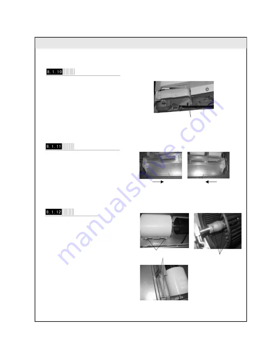
Disassemble Mounting Plate Sub-assy of Swing Motor
Use screwdriver to screw off the screw shown
in the figure. (Fig 8-15)
(Fig 8-15) Screw
Disassemble Left and Right Side Plate Foam Sub-ass
Left Side Plate Foam
Sub-assy
Right Side Plate Foam
Sub-assy
Follow the shown direction to remove the left
and right side plate foam sub-assy. (Fig 8-16)
(Fig 8-16)
Disassemble Fan Motor Assy
Press downward the clasps fitting the front and
rear propeller housings, then pull upward to
remove the front propeller housing (refer to
Figure 8-17).
Hold the clasp position of the rear propeller
housing and pull upward to remove the rear
propeller housing (refer to Figure 8-18).
Use special tool to screw off the two holding
screws at the coupling, move the coupling
toward the fan until the coupling and shaft
sub-assy can be removed; use special tool to
remove the holding screw fixing the fan to
remove the fan (refer to Figure 8-19).
Clasp Position (Fig 8-17) Holding Screw
(Fig 8-18)
(Fig 8-19)
Summary of Contents for AIR F24
Page 2: ... 2 ...
Page 3: ... 3 ...
Page 5: ... 5 M Mo od de el l R Re em ma ar rk ks s GE AIR F34 3PH 400V 50Hz R407C ...
Page 6: ... 6 M Mo od de el l R Re em ma ar rk ks s GE AIR F41 3PH 400V 50Hz R407C ...
Page 12: ... 12 Applicable to GE AIR F34 IN GE AIR F41 IN ...
Page 14: ... 14 Applicable to GE AIR F41 OUT Unit mm Bolt Nut Wrench ...
Page 16: ... 16 GE AIR F24 GE AIR F34 6 6 E El le ec ct tr ri ic ca al l D Di ia ag gr ra am m ...


