background image

SymSafe/SymSafe Pro

User Manual

102

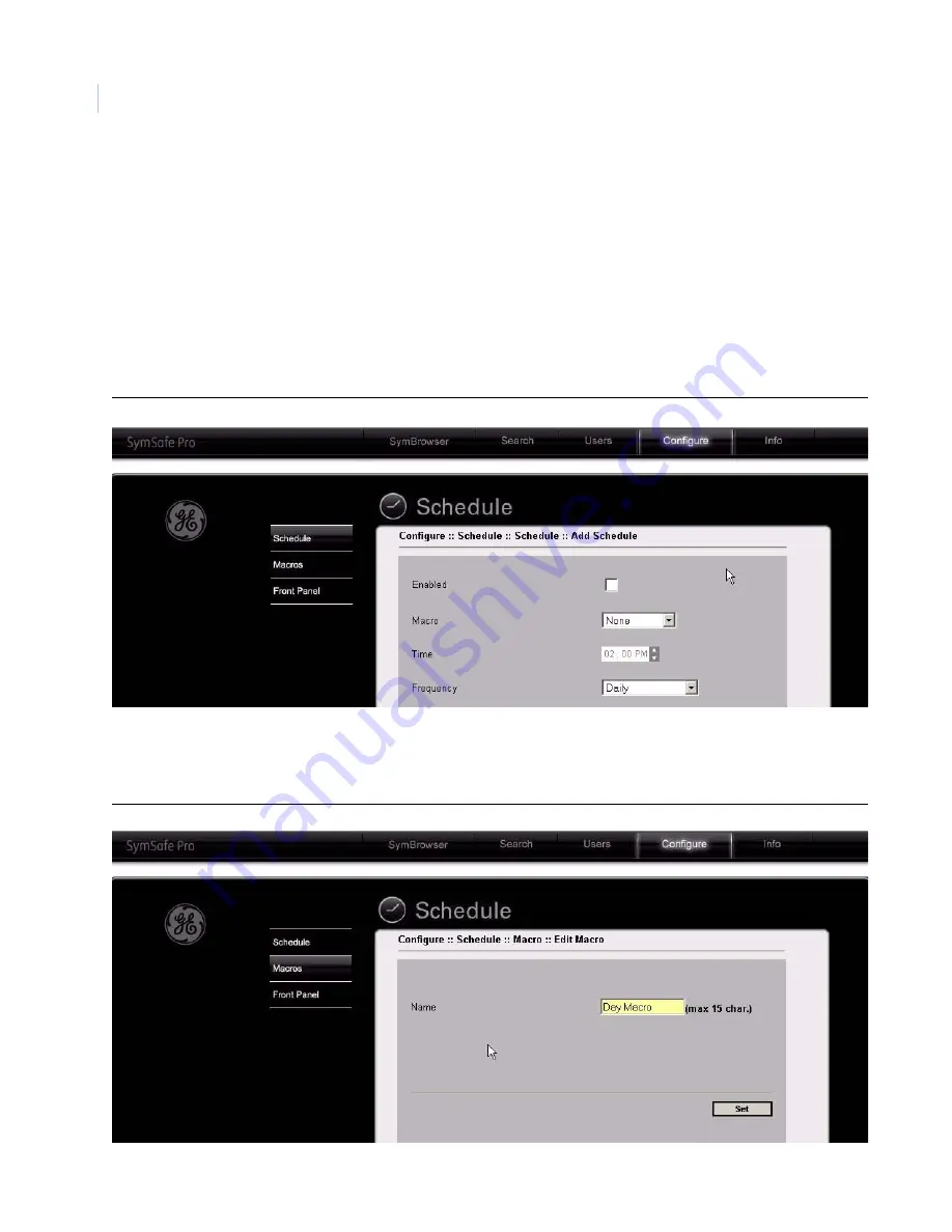
Schedule

Click on the 

Schedule 

link


to display the following scheduling options:

Schedule

Macros

Front  Panel

Schedule

See 

New Schedule

 on page 48 for more detailed information on the features.

Figure 76. Schedule page

Macros

See 

Macros

 on page 49 for more detailed information on the features.

Figure 77. Macros page

Summary of Contents for SymSafe

Page 1: ...SymSafe SymSafe Pro User Manual ...

Page 2: ... or if already installed immediately cease all use of the Software and promptly uninstall all components of the Software 1 Definitions The following definitions apply to this document a GE SECURITY with respect to title to or warranty of the Software means GE Security Inc a Delaware corporation b Software means SymNav the executable software or firmware programs and accom panying documentation ins...

Page 3: ... the date of delivery Media Warranty Period Except as specifically provided therein any other software and any hardware furnished with or accompanying the Software is not warranted by GE SECURITY Your exclusive remedy under this limited warranty for nonconforming Software shall be repair or replacement of the Software at the sole discretion of GE SECURITY To obtain a repair or replacement of nonco...

Page 4: ...ment is the complete and exclusive statement of the agreement between You and GE SECURITY and supersedes any proposal or prior agreement oral or written and any other communication relating to the subject matter of this agreement Intended use Use this product only for the purpose it was designed for refer to the data sheet and user documentation For the latest product information contact your loca...

Page 5: ...nting 7 Passwords 8 Default IP Addresses 8 Chapter 2 Connections and Controls 9 Front Panel Controls and Features 10 Back Panel Connections 12 Camera Inputs 12 Audio Inputs and Output 13 Alarm Inputs 13 USB connectors 13 Ethernet Port 14 RS 485 RS 422 I O connectors 14 RS232 Port 15 VGA connector 15 Monitor A B composite output 16 Alarm out connector 16 Power Connector 16 Connection Diagrams 17 Th...

Page 6: ...reen displays 24 How to change the display presets 25 How to enter Cameo mode 25 How to display Sequencing 25 How to enter Playback mode 25 How to Search using Disk Analysis 26 How to Search using the Filters Screen 26 How to archive from the Search screen 26 How to use the Archive screen 27 27 How to Setup and stream an IP camera to a SymSafe 27 How to setup a KTD 405 keypad to work with the SymS...

Page 7: ...m Inputs and Outputs 55 Group Alarms 57 The Users menu 58 Add New User 58 Edit Users 59 The Network menu 60 IP Settings 61 IP Advanced 62 Muticast Video Streaming Overview 62 Services 64 Streaming 65 Serial Passthrough 66 Email TCP Notification 67 Email Setup 68 Notification Setup 69 The Display menu 70 The System menu 71 Front Panel 71 Time Date 72 Security 74 Languages 75 Disk Tools 76 Serial Co...

Page 8: ...4 Chapter 6 Searching and Archiving 127 Searching 128 The Disk Analysis Screen 128 Search Filters 129 Date and Time Search 129 Camera Motion Search 130 Daily Hours Search 130 Search For Search 131 Search Results 132 Archiving 133 Archive Start screen 134 Fullscreen Search Results Preview 135 SymPlayer 136 Chapter 7 Technical Specifications 137 Technical Specifications 138 General 138 Connections 1...

Page 9: ...ix Chapter 8 Maintenance support 143 Contacting technical support 144 Online publication library 144 ...

Page 10: ...SymSafe SymSafe Pro User Manual x ...

Page 11: ...ou right require before you begin installing configuring and using your SymSafe SymSafe Pro In this chapter Introduction 2 Conventions used in this document 2 Safety terms and symbols 3 Product overview 4 Features 4 Product contents 5 Installation Environment 5 Associated Equipment 6 Rack Mounting 7 Passwords 8 Default IP Addresses 8 Chapter 1 Introduction ...

Page 12: ... 144 for instructions on accessing our online publication library Note A qualified service person complying with all applicable codes should perform all required hardware installation Conventions used in this document The following conventions are used in this document SymSafe4 2 160 SymSafe Pro4 2 320 SymSafe4 2 320 SymSafe Pro4 2 640 SymSafe4 2 640 SymSafe Pro4 2 1T SymSafe8 2 160 SymSafe Pro8 2...

Page 13: ...terms may appear in this manual CAUTION Cautions identify conditions or practices that may result in damage to the equipment or other property WARNING Warnings identify conditions or practices that could result in equipment damage or serious personal injury ...

Page 14: ...nnel composite video input output connection 6 video quality settings Triplex functionality Auto detect video mode NTSC or PAL on startup VGA and composite video outputs Records up to 30 frames per second NTSC of real time video Records up to 25 frames per second PAL of real time video Multi level password protection Continuous recording in disk overwrite mode An easy to use on screen display OSD ...

Page 15: ...te s AC power is stable and within the rated voltage of the external power supply If the site s AC power is likely to have spikes or power dips use power line conditioning or an Uninterruptable Power Supply UPS Ventilation Install the unit in a well ventilated area Take note of the locations of the cooling vents in the unit s enclosure and ensure that they are not obstructed Temperature Observe th...

Page 16: ...the unit Associated Equipment Associated equipment you might need Analog cameras 4 8 or 16 SymVeo SV XP3 IP Cameras 2 Analog or flat panel monitor to view VGA video Alarm input devices Pressure sensors motion detectors etc Alarm output devices Buzzers Sirens Flashing Lights etc A PC connected by Ethernet Microphones 2 with amplification Speakers to hear audio Symnet encoder decoder to receive or s...

Page 17: ...to installing the equipment in an environment compatible with the maximum ambient temperature 40 specified by the manufacturer Reduced Air Flow Installation of the equipment in a rack should be such that the amount of air flow required for safe operation of the equipment is not compromised Mechanical Loading Mounting of the equipment in the rack should be such that a hazardous condition is not ach...

Page 18: ...e IP addresses should be changed before you connect to your IP network Contact your network administrator to obtain your network specific addresses Table 1 Default passwords Password name Program Changeable by user Default password Log In Password user 1 On Screen Display OSD Yes through the Main menu 111111 Log In Password user 2 On Screen Display OSD Yes through the Main menu 222222 Log In Passw...

Page 19: ...tures 10 Back Panel Connections 12 Camera Inputs 12 Audio Inputs and Output 13 Alarm Inputs 13 USB connectors 13 Ethernet Port 14 RS 485 RS 422 I O connectors 14 RS232 Port 15 VGA connector 15 Monitor A B composite output 16 Alarm out connector 16 Power Connector 16 Connection Diagrams 17 The Remote Controller 19 Chapter 2 Connections and Controls ...

Page 20: ...mode Search button Press to display the Search and Disk Analysis screen Live button Press to stop all video playback and return to showing live video Replay button Press to jump the play marker back x seconds Configured in Front Panel on page 71 Fast reverse button Press to play video in reverse Press again to increase speed Play reverse button Press to play video in reverse at 1X speed Pause butt...

Page 21: ... fullscreen In Setup mode used to input numerical data Camera LED Analog 1 16 and IP 1 2 Green solid bright Connected and working properly awake mode Green solid dim Connected and working properly stealth mode Red flashing Alarm detected not acknowledged or in Videoloss Red solid Alarm detected acknowledged Off camera is disabled Recording LED Green solid bright Recording properly awake mode Green...

Page 22: ...is connected to the 2nd BNC connector of the same camera input Make sure there is 75 Ohm termination at the end of the video line if the signal is looped through the SymSafe Connector Use Video In Out Camera Inputs 1 4 8 or 16 BNC connector looping and auto terminating Audio inputs 2 channels of line level audio inputs with RCA connectors Alarm inputs 4 8 or 16 channels of alarm inputs USB connect...

Page 23: ... Industry compatible USB connectors for use with flashdrives for updating the SymSafe Cable 75 Ohm coaxial Connectors BNC Auto terminating Yes Passive looping Yes Audio input RCA jack 315 mV 40k Ohms Unbalanced Audio out RCA jack 315mV 600 Ohms Unbalanced Table 5 Alarm Inputs Alarm IN connector Pin Signal Pin Signal Pin Signal Pin Signal 1 Alarm Input 1 N Open 5 Alarm Input 5 N Open 9 Alarm Input ...

Page 24: ... system RS 485 RS 422 I O connectors These 2 serial I O ports can be configured as either RS 485 or RS 422 and are used for Pan Tilt Zoom control of PTZ cameras Use Serial Communications on page 78 to configure these ports See tables 6 and 7 for the serial pinouts for each configuration Ethernet 10 100 1000 Base T auto sensing Wire type Cat 5e 6 Connector type RJ 45 Maximum cable length 328 feet 1...

Page 25: ...e Serial Communications on page 78 to configure this port VGA connector The 15 pin VGA connector is provided for connection to a standard VGA monitor for monitoring video Table 7 RS 422 1 and 2 port pinouts Port type Pin Description RS 422 1 1 TX 2 TX 3 Ground 4 RX 5 RX RS 422 2 6 TX 7 TX 8 Ground 9 RX 10 RX Table 8 RS232 port pinouts Pin Description 1 DCD 2 RX 3 TX 4 DTR 5 Grounded 6 Not connecte...

Page 26: ... notification devices such as sirens and warning lights Power Connector Plug the power cord into the power cord connector and then into a properly rated wall socket Once power is applied to the unit it will begin its power up procedure The unit will begin by displaying the software version on Monitor A then the unit will begin recording automatically Cable 75 Ohm Connectors BNC Table 9 Alarm out p...

Page 27: ...Chapter 2 Connections and Controls 17 Connection Diagrams Use the figures on the following pages a visual guide to connect the various peripherals to the SymSafe Figure 5 Rear panel connection diagram ...

Page 28: ...SymSafe SymSafe Pro User Manual 18 Figure 6 Sample network diagram ...

Page 29: ...d to operate many of the main functions of the SymSafe and can be programmed to work with up to 4 SymSafe s Figure 7 The remote control unit Note The remote controller can be programmed with a unique address 1 4 so that the controller will only be able to communicate with unit s with that address See Front Panel on page 52 to program ...

Page 30: ...SymSafe SymSafe Pro User Manual 20 ...

Page 31: ...he display to a full screen IP view 24 How to view multiscreen displays 24 How to change the display presets 25 How to enter Cameo mode 25 How to display Sequencing 25 How to enter Playback mode 25 How to Search using Disk Analysis 26 How to Search using the Filters Screen 26 How to archive from the Search screen 26 How to use the Archive screen 27 How to setup a KTD 405 keypad to work with the Sy...

Page 32: ... and Playback mode starts Cameo mode Search button Press to display the Search and Disk Analysis screen Live button Press to stop all video playback and return to showing live video Replay button Press to jump the play marker back x seconds Configured in Front Panel on page 71 Fast reverse button Press to play video in reverse Press again to increase speed Play reverse button Press to play video i...

Page 33: ...nalog IP button Controls which camera is selected when the camera buttons are pressed Camera buttons Push to display the selected camera in fullscreen In Setup mode used to input numerical data Recording LED Green solid bright Recording properly awake mode Green solid dim Recording properly stealth mode Red flashing Recording failure not acknowledged Red solid Recording failure acknowledged Networ...

Page 34: ...live and playback functions and access the menus press the Mon A button 2 To change the display of live video on the secondary display press the Mon B button How to change the display to a full screen analog view 1 Press the Analog button if the LED is not lit to enable the analog camera buttons 2 Press the camera number 1 16 of the camera you wish to view full screen How to change the display to ...

Page 35: ...s the IP or Analog button followed by a camera number button How to display Sequencing The sequencing feature allows a camera to be displayed briefly on screen before advancing to the next camera in the sequence list The default sequence list displays each camera in numerical order From Full Screen 1 Press any camera number to enter fullscreen mode 2 Press the Sequence button to begin automatic se...

Page 36: ...or Alarms Only 3 Press enter to change the filter mode and settings 4 Change the filter as desired and Press Menu button to return to the top level menu 5 When you have set all the filters Select Search Now and Press enter The Thumbnail Previews screen will appear 6 From the Thumbnail Previews screen select the video you wish to review and press enter to begin previewing the video in playback How ...

Page 37: ...name of the file to be exported Select Done and press enter when finished 5 Press the down arrow to select the archive length The Archive Stop Time was set when you pressed the Archive button Press enter and adjust the length to change the Start Time Press enter to confirm the length 6 Press the down arrow to select the Include Player checkbox Check to include the GE SymPlayer or uncheck if you ha...

Page 38: ...he KTD 405 I O box to the SymSafe Bus 1 485 port KTD 405 I O box pin RS485 A to SymSafe Serial I O Bus 1 485 pin 1 KTD 405 I O box pin RS485 B to SymSafe Serial I O Bus 1 485 pin 2 2 Verify the serial communication settings on Bus 1 of the SymSafe a Go to the System Serial Communication Bus 1 menu and verify the following Bus 1 Type RS 0485 Protocol Kalatel Baud Rate 9600 DVR Addr 1 3 Enter Zone m...

Page 39: ...e Seq button to exit programming mode 9 You should now be able to select the IP camera by pressing the magnifying glass icon KTD 405 keypad mapping to SymSafe front panel Figure 9 KTD 405 panel buttons Table 12 KTD 405 to SymSafe front panel mapping KTD 405 Keypad SymSafe front panel function Replay button In playback mode touch to jump the play marker back x seconds Play forward button plays vide...

Page 40: ...se or counter clockwise to jog video forward or reverse In setup mode emulates the Enter button Toggles in and out of editable fields esc Emulates the Menu button Push to enter OSD mode or to discard changes in menus Alarm Emulates the Alarm button Push to acknowledge all alarms View Emulates the Display button Push to cycle through available multiscreens Use with the 2 5 number buttons Seq Emulat...

Page 41: ...ogram how the SymSafe operates from setting up the password levels to the record rates of the cameras In this chapter Log In 32 Cameras menu 35 The Schedule menu 47 The Users menu 58 The Network menu 60 The Display menu 70 The System menu 71 The Info menu 83 Chapter 4 Programming the SymSafe ...

Page 42: ...ower to the SymSafe To setup a user press the Menu button on the front panel The initial Log In screen will appear Note A maximum of 5 users on the basic SymSafe and 10 users on the SymSafe Pro can be logged in at the same time Figure 10 The Log In screen Use the arrow buttons to navigate select a user and press the Enter button The Enter Your Pin screen will appear Figure 11 The Enter Your Pin sc...

Page 43: ... to enter the password When completed navigate to the Done button and press Enter The Main OSD menu will appear Main Menu The Main menu contains the following sub menus Cameras Schedule Alarms Users Network Display System Info Log Out Table 13 Default passwords Password name Default password PIN User 1 111111 User 2 222222 User 3 333333 ...

Page 44: ...l 34 Figure 12 The Main menu Note GE recommends that after you have completed your initial Log In you should setup up your users passwords and access levels for security reasons See The Users menu on page 58 for complete information ...

Page 45: ...h to configure and press the Enter button The analog camera or IP camera edit menu will display Note The camera number can be selected by using the arrow buttons on the front panel the camera number buttons on the front panel or the camera number buttons on the remote controller Analog Camera menu The Analog Camera menu contains the following options and their settings Recording Rates Alarm Input ...

Page 46: ...ns Menu Setting Options Record Input Live Disable Live Record Record Quality 1 low quality to 6 high quality Resolution D1 704x480 2CIF 704x240 CIF 352x240 Record Mode Always Alarm only Event Alarm Covert Enable or disable Covert means the camera is recording but the display is turned off Low latency Enable or disable Enabling low latency increases the response time but lowers the quality Normally...

Page 47: ...n also set the pre and post recording times for both event and alarm conditions Figure 15 The Camera Duration Rates menu Table 15 The Cameras Rates options Menu Setting Options Timelapse Rate 2 5 10 15 30 fps frames per second Event Rate 2 5 10 15 30 fps Alarm Rate 2 5 10 15 30 fps Pre Event 0 5 minutes Post Event 0 5 minutes Pre Alarm 0 5 minutes Post Event 0 5 minutes ...

Page 48: ...ect 1 or more alarm inputs to the currently selected camera Press the enter button to enter the edit mode You can enable or disable video loss here When video loss is enabled it will be reported as an alarm on the selected camera Figure 16 The Cameras Alarm Inputs menu ...

Page 49: ... motion in a scene The Low setting is the most sensitive to motion The Medium setting will filter out most false alarm situations due to sudden luminance changes over the whole scene clouds passing over The High setting will filter out sudden luminance changes as well as spurious motion events that do not persist for a number of frames a bird flying past the lens Motion edit screen Press the enter...

Page 50: ...is menu to change the camera title Press the enter button to access the on screen keypad to edit the title Use the arrow buttons to navigate and the enter button to select the various alphanumeric characters available Figure 18 The Camera Camera Title menu ...

Page 51: ...elected cameras video image You can also enable or disable the Automatic Gain Control AGC here Figure 19 The Camera Adjust Video menu Table 17 The Camera Adjust Video settings Menu setting Options Brightness 0 99 Contrast 0 99 Saturation 0 99 Automatic Gain Control Enable disable ...

Page 52: ... Select the cameras to copy the selected camera s parameters Navigate to the Copy Now command to execute Note The Copy Setting command copies all the selected camera s configurable settings Figure 20 The Camera Copy Settings menu IP Camera menu The IP Camera menu contains the following options and their settings Recording Rates Alarm Input Camera Title Copy Setting ...

Page 53: ...is menu to enable or disable the covert feature of the IP camera selected Figure 21 The IP Camera Recording menu Table 18 Cameras Recording options Menu Setting Options Record Input Live Disable Live Record Source Address IP address of selected camera Record Mode Always Alarm only Event Alarm Covert Enable or disable Covert means the camera is recording but the display is turned off ...

Page 54: ...ions Figure 22 The IP Camera Duration Rates menu Table 19 IP Cameras Duration Rates Note These settings will vary depending on the Time Lapse settings Menu Setting Options Pre Event In seconds varies with bitrate Post Event In seconds varies with bitrate Pre Alarm In seconds varies with bitrate Post Event In seconds varies with bitrate ...

Page 55: ...deo loss here When video loss is enabled it will be reported as an alarm on the selected IP camera Figure 23 The IP Camera Alarm Input menu Camera Title Use this menu to change the camera title Press the enter button to access the on screen keypad to edit the title Use the arrow buttons to navigate and the enter button to select the various alphanumeric characters available Figure 24 The IP Camera...

Page 56: ...ngs to other available cameras Press enter to access the edit area Select the cameras to copy the selected camera s parameters Navigate to the Copy Now command to execute Note The Copy Setting command copies all the selected camera s configurable settings Figure 25 The IP Camera Copy Settings menu ...

Page 57: ...ton The Schedule menu will appear Figure 26 The Schedule menu The Schedule menu contains the following options and their settings New Schedule Schedule start times for macros A maximum of 30 schedules may be created Macros Create and select macros A maximum of 15 macros for the basic model and 30 macros can be setup Front Panel Assign a camera number button to a macro for front panel execution ...

Page 58: ... specific macro Press enter to access the edit area Figure 27 The Schedule New Schedule menu Table 20 The Schedule New Schedule options Menu Setting Options Enable Enable or disable Macros None or Names of defined macros Time Define hour and minute of execution Frequency Daily M F Weekends Weekly ...

Page 59: ...Chapter 4 Programming the SymSafe 49 Macros Use this menu to create a new macro or edit a previously created macro Press enter to access the edit area Figure 28 The Schedule Macros Menu ...

Page 60: ... a name to the macro Include Display Settings Check On or Off to show the display options selected in the Display menu Store Settings All Save all the settings in the macro programming tree Only changed Saves only those settings that have been changed during the macro programming Run Macro Now Select and press enter to run the macro immediately Begin Recording Select and press enter to start recor...

Page 61: ...lude Display Settings Check On or Off to show the display options selected in the Display menu Store Settings All Save all the settings in the macro programming tree Only changed Saves only those settings that have been changed during the macro programming Run Macro Now Select and press enter to run the macro immediately Begin Recording Select and press enter to start recording keystroke Press the...

Page 62: ...creen press enter to move to edit mode b Select Create New Macro and press enter c In the Name field press enter d Use the on screen keypad to enter Camera 1 Off Press Done when finished e Navigate to Begin Recording and press enter f Select Camera and press enter Select camera 1 g Press enter select Input and press enter Select Disable and press enter h Press the Alarm button to finish recording ...

Page 63: ... command and press enter d Select Camera 1 Off and press enter e Move the cursor to the Time command and press enter f Use the arrow buttons to select 7 p m and press enter g Move the cursor to the Save Schedule Macros command and press enter 4 Schedule macro Camera 1 On a Navigate to the Schedule menu and press enter on New Schedule to move to edit mode b Press enter to enable the schedule c Move...

Page 64: ...Buzzer Email Alarm Output 1 4 Figure 32 The Alarms Notification menu Table 23 Notification descriptions Notification Description Disk Fail When a hard disk failure is detected Disk Full When a hard disk is at capacity Net Fail When a network failure is detected Fan Fail When a fan failure is detected Power On On shutdown a flag is set to indicate successful shutdown If no flag is detected at bootu...

Page 65: ...zzer that has been linked to Camera or Silent Alarms Figure 33 The Alarms Silent Alarm menu Alarm Inputs and Outputs Use this menu to attach the specified alarm inputs and outputs to the selected camera Figure 34 The Alarms Alarms Inputs and Outputs menu Note Select Analog or IP and camera number ...

Page 66: ...latched for the amount of time specified in the Timeout field Input type Normally Open Normally Closed Timeout 0 59 minutes if Timeout selected in Input mode Macro None Select Macro name to select Macro Name you must have created and named a macro in the Schedule Macros menu Protect Enable or Disable Buzzer Enable or Disable Email Enable or Disable Alarm Out 1 Enable or Disable Alarm Out 2 Enable ...

Page 67: ...Chapter 4 Programming the SymSafe 57 Group Alarms Use this menu to enable or disable group alarms Press enter on the selected group to modify the group alarm properties Figure 36 The Group Alarms menu ...

Page 68: ...n to a SymSafe at one time Figure 37 The Users menu The Users menu contains the following options and their settings Add New User Edit Users 1 3 Add New User Use this menu to add a new user assign a password and select the users access level Press enter to enter the edit window and use the keypad to create the user s name Figure 38 The Users Add New User menu ...

Page 69: ...r options Menu options Settings Login Name Press enter to enter the edit window and use the keypad to edit the user s name Password Enter from 4 to 8 characters Access Level Operator Access to Display Info menus only Manager Access to Users Display and Info menus only Administrator Full access to all menus Timeout 0 999 minutes At 0 minutes the unit will never timeout log out Remove this User Sele...

Page 70: ...nu Highlight the Network icon and press the enter button The Network menu will appear The Network menu contains the following options and their settings IP Settings IP Advanced Services Streaming Passthrough Notification Email Setup Notification Setup ...

Page 71: ... selected Subnet Mask Consult with a qualified network administrator or IT professional to configure these settings if DHCP is not selected Gateway Consult with a qualified network administrator or IT professional to configure these settings if DHCP is not selected Dynamic Name Server 1 Consult with a qualified network administrator or IT professional to configure these settings if DHCP is not sel...

Page 72: ...he default Sets the maximum TCP packet size Net Limit None 0 3999 Kbps Listen Port 1024 is the default This is the port that the SymSafe uses to listen for streaming commands Streaming Protocol UDP TCP Multicast IP address 230 0 0 0 is the default This must match between devices Streaming Port 8090 is the default setting for the stream Sender Control Enable or Disable Must be enable to send IP vid...

Page 73: ...tagram Protocol is a connectionless protocol that like TCP runs on top of IP networks Unlike TCP IP UDP IP provides very few error recovery services offering instead a direct way to send and receive datagrams over an IP network It s used primarily for broadcasting messages over a network A UDP sender sends out digital video over an IP network A UDP sender can be the SymDec 4 SymSafe Symveo IP Came...

Page 74: ...treams each Services Use this menu to define the parameters of the networks services Consult with a qualified network administrator or IT professional to configure these settings Figure 42 The Network Services menu Table 28 The Network Services menu options Menu Options Settings HTTP Port 80 is the default Select from 0 to 65535 To disable SymBrowser access set the port to 0 NTP Server 1 IP Addres...

Page 75: ...1 Navigate to the Network IP Advanced Multicast setting Set the Multicast address of the stream you are going to receive to 230 123 456 789 Note Note that if there are four units sending multicast streams each unit must have the same multicast stream address 2 Navigate to Cameras IP Camera 1 Set the source address to the physical address of the unit sending a multicast video stream You can repeat ...

Page 76: ...a 2 Select he Remote IP and the Port number of the unit you want to send receive serial pass through data Both units must have the same port number 3 The Serial Port option specifies which port you want to send receive serial data 4 Make sure that the Auto Connect checkbox is checked as it maintains the serial port as active Figure 44 The Network Serial Passthrough menu Table 30 The Network Serial...

Page 77: ... the method of notification email or TCP for the following incidents Notify on Record Notify on Archive Notify on Menu Access Notify on Power Up Notify on Connection Notify on Alarm Notify on Video Loss Select a checkmark in either box to enable Figure 45 The Network Notification menu ...

Page 78: ...etwork Email Setup menu options Menu Options Settings Email 1 Email address where notification is to be sent SMTP Server Enter a valid Simple Mail Transfer Protocol SMTP name SMTP Port Default is 25 SMTP Authorization Check to enable or disable SMTP User Enter a valid SMTP username SMTP Password 1 to 10 characters SMTP SSL Enable or disable SSL Secure Sockets Layer encryption ...

Page 79: ...7 The Network Notification Setup menu Table 32 The Network Notification Setup menu options Menu Options Settings Alarm Server 1 Enter a primary alarm server IP address Alarm Server 2 Enter a backup alarm server IP address Alarm port Default is 1027 Choose from 1024 to 32767 Alarm Minutes 0 to 299 Minutes after the event to send notification ...

Page 80: ...ppear Figure 48 The Display menu The Display menu contains the following options and their settings Current Time Date Record Playback Speed Playback Time Date Camera Titles Text Insertion Inserts serial based text Text Timeout 0 99 minutes the length of time the text is displayed in minutes Enter a checkmark in the box to enable ...

Page 81: ...Front Panel Use this menu to setup the front panel features The remote control ID setup is also configured here Figure 49 The System Front Panel menu Table 33 The System Front Panel menu options Menu Options Settings Dwell Monitor A 0 99 seconds Dwell Monitor B 0 99 seconds Replay 0 999 seconds Panel Tone Enable or disable Lights Off Enable or disable Remote COntrol ID Select from disable and 1 to...

Page 82: ... menu to setup the time and date features of the SymSafe Figure 50 The System Time and Date menu Table 34 The System Time and Date menu options Menu Options Settings Current Time Press the enter button when selected to enter the time Time Format 12 or 24 ...

Page 83: ... West Central Africa GMT 02 00 Athens Istanbul Minsk Bucharest Cairo Harare Pretoria Helsinki Riga Tallinn Jerusalem GMT 03 00 Baghdad Kuwait Riyadh Moscow St Petersburg Volgograd Nairobi GMT 03 30 Tehran GMT 04 00 Abu Dhabi Muscat Baku Tbilisi Yerevan GMT 04 30 Kabul GMT 05 00 Ekaterinburg Islamabad Karachi Tashkent GMT 05 30 Calcutta Chennai Mumbai New Delhi GMT 05 45 Kathmandu GMT 06 00 Almaty ...

Page 84: ...se features Selecting Any allows any user type access to modify these security operations Figure 51 The System Security menu Table 35 The System Security men options Menu Options Settings Front Panel Any Administrator Operator Manager Macros Any Administrator Operator Manager Search Any Administrator Operator Manager Archive Any Administrator Operator Manager Covert Any Administrator Operator Mana...

Page 85: ... Languages Use this menu to setup the language and currency usage Figure 52 The System Language menu Table 36 The System Language men options Menu Options Settings Language English Currency select currency type for text insertion purposes ...

Page 86: ...SymSafe SymSafe Pro User Manual 76 Disk Tools Use this menu to access the SymSafe s hard disk maintenance features Figure 53 The System Disk Tools menu ...

Page 87: ... The unit overwrites all previously recorded data Recording stops before the unit overwrites any of the newly recorded data data from the current record session When the end of the disk is reached the unit displays an on screen message indicating that the disk is full and the unit has stopped recording User must acknowledge the on screen message by clicking the Enter button The unit will continue ...

Page 88: ...nu Options Settings Bus 1 Type RS 485 or RS 422 Protocol Kalatel or Passthrough Kalatel is used for controlling PTZ cameras using SymNav Passthrough is referring to serial passthrough which is setup in the Network Passthrough dialog If you set Bus 1 to serial passthrough then the Protocol options must be set to Passthrough Baud Rate 300 1200 2400 4800 9600 19200 DVR Address 0 199 Bus 2 Type RS 485...

Page 89: ...panel Figure 55 The System Serial Communication RS 232 Table 39 The System Serial Communication RS 232 options Menu Options Settings Protocol Text Insertion or Serial Passthrough Baud Rate 300 1200 2400 4800 9600 19200 28800 38400 357600 115200 Data Bits 5 6 7 8 Parity None Even Odd Stop Bits 1 or 2 Flow Control None Xon Xoff ...

Page 90: ... 1 Insert a USB flashdrive with the flash upgrade file into one of the USB ports 2 Navigate to the Upgrade Now command and press the enter button 3 The SymSafe will reboot when completed Note The flash upgrade file must be in the root directory of the flashdrive Do not remove power while an upgrade is in process Figure 56 The System Firmware Upgrade menu ...

Page 91: ...save settings to a USB flashdrive Figure 57 The System Setting Tool Table 40 The System Setting Tool option Menu Options Settings Restore Factory Settings Select Yes to restore Load Settings Select Yes to load settings from a USB Flashdrive Save Settings Select Yes to save settings to a USB Flashdrive ...

Page 92: ...SymSafe SymSafe Pro User Manual 82 Shutdown Use this menu to shutdown the SymSafe safely Navigate to the Shutdown Now command and press the enter button Figure 58 The System Shutdown menu ...

Page 93: ...ghlight the Info icon and press the enter button The Info menu will appear The Info menu contains the following options and their settings Health The Health menu display information on the following System Disk 1 2 Fans 1 4 Figure 59 The Info Health menu ...

Page 94: ...o User Manual 84 System The System menu display information on the following Model Serial Number Hostname Software Version Software Date BL Version FPGA Version SymPlayer Version Disk Size Figure 60 The Info System menu ...

Page 95: ... Programming the SymSafe 85 Network The Network menu display information on the following IP Address MAC Address DHCP Lease Expires Last DDNS Update Status Last DNS Update Success Figure 61 The Info Network menu ...

Page 96: ...ess 001755f33906 12 21 2006 11 06 53 Network Link Down 12 21 2006 11 06 53 System Start 12 29 2006 04 43 59 Network Link Down 12 29 2006 04 43 59 System Start 01 05 2007 04 56 59 Network Link Down 01 05 2007 04 56 59 System Start 01 05 2007 05 05 08 Network Link Down 01 05 2007 05 05 08 System Start 01 10 2007 03 03 51 Network Link Down 01 10 2007 03 03 51 System Start 01 10 2007 03 45 06 Network ...

Page 97: ...dded SymBrowser In this chapter SymNav 88 Minimum System Requirements 88 Installing SymNav software from CD ROM 88 Starting SymNav software 88 The SymBrowser Webserver 90 Search 91 User 92 Configure options 93 Cameras 94 Schedule 102 Alarms 104 Network 108 System 115 Info 122 Symbrowser 124 Chapter 5 SymNav and SymBrowser ...

Page 98: ...llation as they appear Note If Autorun is not enabled on your PC choose Run from the Start Menu then type d setup exe where d is the drive letter of your CD ROM and click OK Follow the instructions as they appear on your screen Starting SymNav software To start the SymNav software double click on the SymNav software desktop icon or choose Programs from the Start menu and then select SymNav softwar...

Page 99: ...Chapter 5 SymNav and SymBrowser 89 Figure 63 The SymNav main operation screen ...

Page 100: ...n the unit s IP address 192 168 1 82 or hostname see network settings page in the address field and click enter Note When launching SymBrowser checks your system for the correct files If they are not detected SymBrowser will attempt to load them Accept all General Electric signed content to allow the files to be loaded 3 The Enter Network Password screen will appear Enter your user name and passwo...

Page 101: ... display the following user options Disk Analysis screen Search by Dates Camera Motion Daily Hours selection Search for Alarms Event and Text options See Searching on page 128 for more detailed information on how to use these features Figure 65 The Search Disk Analysis screen ...

Page 102: ... user options Add User Edit User Add User Click on the Add User link to display the Add New page On this page you can Enter a login name Create a password Enter a timeout in minutes and Set the user s access levels Figure 66 Add new options Note Up to 24 users can be logged on at the same time ...

Page 103: ...s page you can Edit a user s login name Change a user s password Change the user s timeout in minutes Modify the user s access levels Delete or Save the user Figure 67 The Edit User page Configure options Clicking on the Configure link will display the following options Cameras Schedule Alarms Network System ...

Page 104: ...Cameras link to display the Configure Cameras page Clicking on the camera that you want to configure launches the camera edit options Recording Rates Duration Alarm Input Motion Detection Camera Title Adjust Video Copy Setting Figure 68 Configure Camera page ...

Page 105: ...Chapter 5 SymNav and SymBrowser 95 Recording See the Recording Menu on page 36 for more detailed information on the features Figure 69 Cameras edit recording page ...

Page 106: ...SymSafe SymSafe Pro User Manual 96 Rates Duration See Duration Rates on page 37 or more detailed information on the features Figure 70 Camera edit Rates Duration page ...

Page 107: ...Chapter 5 SymNav and SymBrowser 97 Alarm Input See Alarm Input on page 38 for more detailed information on the features Figure 71 Camera edit Alarm Input page ...

Page 108: ...SymSafe SymSafe Pro User Manual 98 Motion Detection See Motion Detection on page 39 for more detailed information on the features Figure 72 Camera edit Motion Detection page ...

Page 109: ...Chapter 5 SymNav and SymBrowser 99 Camera Title See Camera Title on page 40 for more detailed information on the features Figure 73 Camera edit Camera Title page ...

Page 110: ...SymSafe SymSafe Pro User Manual 100 Adjust Video See Adjust Video on page 41 for more detailed information on the features Figure 74 Camera edit Adjust video page ...

Page 111: ...Chapter 5 SymNav and SymBrowser 101 Copy Settings See Copy Settings on page 42 for more detailed information on the features Figure 75 Camera Edit Copy settings page ...

Page 112: ...o display the following scheduling options Schedule Macros Front Panel Schedule See New Schedule on page 48 for more detailed information on the features Figure 76 Schedule page Macros See Macros on page 49 for more detailed information on the features Figure 77 Macros page ...

Page 113: ...Chapter 5 SymNav and SymBrowser 103 Front Panel See Front Panel on page 52 for more detailed information on the features Figure 78 Front panel page ...

Page 114: ...Click on the Alarm link to display the following alarm options System Notification Silent Alarm Alarm Inputs Outputs System Notification See Notification on page 54 for more detailed information on the features Figure 79 System Notification page ...

Page 115: ...tailed information on the features Figure 80 Silent Alarm page Alarm Inputs and Outputs Figure 81 Alarm Inputs Outputs page Select a camera number to launch the Alarm Input Outputs edit page See Alarm Inputs and Outputs on page 55 for more detailed information on the features ...

Page 116: ...SymSafe SymSafe Pro User Manual 106 Figure 82 The Alarms Inputs Outputs edit page ...

Page 117: ...Chapter 5 SymNav and SymBrowser 107 Group Alarms See Group Alarms on page 57 for more detailed information on the features Figure 83 Group Alarms page ...

Page 118: ...ink to display the following network options IP Setting IP Advanced Services Streaming Serial Pass Through Network Notification Email Setup Notification Setup IP Setting See IP Settings on page 61 for more detailed information on the features Figure 84 IP Setting page ...

Page 119: ...Chapter 5 SymNav and SymBrowser 109 IP Advanced See IP Advanced on page 62 for more detailed information on the features Figure 85 IP Advanced page ...

Page 120: ...SymSafe SymSafe Pro User Manual 110 Services See Services on page 64 for more detailed information on the features Figure 86 Services page ...

Page 121: ...Chapter 5 SymNav and SymBrowser 111 Streaming See Streaming on page 65 for more detailed information on the features Figure 87 Streaming settings page ...

Page 122: ...SymSafe SymSafe Pro User Manual 112 Serial Passthrough See Serial Passthrough on page 66 for more detailed information on the features Figure 88 Serial pass through page ...

Page 123: ...Chapter 5 SymNav and SymBrowser 113 Network Notification See Email TCP Notification on page 67 for more detailed information on the features Figure 89 Network notification page ...

Page 124: ...SymSafe SymSafe Pro User Manual 114 Email Setup See Email Setup on page 68 for more detailed information on the features Figure 90 Email setup page ...

Page 125: ...n Setup See Notification Setup on page 69 for more detailed information on the features Figure 91 Notification setup System Click on the System link to display the following system options Front Panel Time Date Security Language Serial Communication ...

Page 126: ...SymSafe SymSafe Pro User Manual 116 Front Panel See Front Panel on page 71 for more detailed information on the features Figure 92 Front panel page ...

Page 127: ...Chapter 5 SymNav and SymBrowser 117 Time Date See Time Date on page 72 for more detailed information on the features Figure 93 Time Date page ...

Page 128: ...SymSafe SymSafe Pro User Manual 118 Security See Security on page 74 for more detailed information on the features Figure 94 Security page ...

Page 129: ...Chapter 5 SymNav and SymBrowser 119 Language See Languages on page 75 for more detailed information on the features Figure 95 Language page ...

Page 130: ...SymSafe SymSafe Pro User Manual 120 Serial Communication See Serial Communications on page 78 for more detailed information on the features Figure 96 Serial Communication page ...

Page 131: ...Chapter 5 SymNav and SymBrowser 121 Firmware Upgrade See Firmware Upgrade on page 80 for more detailed information on the features Figure 97 Firmware Upgrade page ...

Page 132: ...SymSafe SymSafe Pro User Manual 122 Info Clicking on the Info link will display system and network information System Network System Figure 98 System Info page ...

Page 133: ...Chapter 5 SymNav and SymBrowser 123 Network Figure 99 Network Info page ...

Page 134: ... available Right click on the video to switch from live or playback mode or view full screen High and Low bandwidth buttons High is best with PTZ cameras Live button Frame advance forward and reverse button Replay button Fast reverse playback button Reverse playback button pause button Play button Fast play forward button Analog IP camera select button Camera buttons 1 16 analog 1 2 IP Figure 100 ...

Page 135: ...Chapter 5 SymNav and SymBrowser 125 ...

Page 136: ...SymSafe SymSafe Pro User Manual 126 ...

Page 137: ...hapter Searching 128 The Disk Analysis Screen 128 Search Filters 129 Date and Time Search 129 Camera Motion Search 130 Daily Hours Search 130 Search For Search 131 Search Results 132 Archiving 133 Archive Start screen 134 Fullscreen Search Results Preview 135 SymPlayer 136 Chapter 6 Searching and Archiving ...

Page 138: ...rizontally into 48 equal slices Holding down LEFT and RIGHT will jump the cursor back and forth to the next nearest slice in that direction Additional behaviors include LEFT from Far left scrolls left a half screen if more video is available centering the cursor else the cursor remains at the left end of the video RIGHT from Far right scrolls right a half screen if more video is available centerin...

Page 139: ...f all of the filters If any one filter extends beyond the range of any other such as daily hours being outside the Search by Dates range selected the results should not be negatively effected as the intersection will still be within the smaller of the two spaces Date and Time Search Select Search by Date Time to launch the Date Time Search menu Menu options include All Dates Last x days x number L...

Page 140: ...h the Cam Motion Search menu Menu options include All cameras Motion Detection Select by Camera Figure 103 Search by Camera Motion screen Daily Hours Search Select Search by Daily Hours to launch the Daily Hours Search menu This option searches All Hours Figure 104 Search by Daily Hours screen ...

Page 141: ...g and Archiving 131 Search For Search Select Search by Search For to launch the Search For Search menu Menu options include All Items Text launches on screen keypad Alarms Events Alarms Only Figure 105 Search For screen ...

Page 142: ...ered by date oldest first Default selection is Play of the top left thumbnail Use the arrow buttons to move you through the selection of the thumbnails Arrow indicators on the top and bottom are used to indicate that there are additional video segments on other screens Press enter on any thumbnail to go to full screen preview Figure 106 Search Results screen ...

Page 143: ...keypad Archive Length In minutes Include Video Player Yes or No Camera Selection boxes Size In megabytes Start and Stop parameters Archive Now Starts archiving to selected media Figure 107 The Archive Screen CAUTION Do not use DVD s with paper labels attached to the surface of the DVD The label s surface may become damaged and cause the DVD media to become stuck inside the DVD recorder ...

Page 144: ...ay of the top left thumbnail Use the arrow buttons to move you through the selection of the thumbnails Arrow indicators on the top and bottom are used to indicate that there are additional video segments on other screens Press enter on any selected thumbnail to go to full screen preview Figure 108 The Archive Start screen ...

Page 145: ... video for archive purposes The resulting stop is shown in the summary If no stop is associated with the current video the current date and time are used Protect prevents the selected video from deletion Pro models only Archive brings up the Search Archive screen Close Preview exits preview and search and returns the user to the display screen from which they entered search Hide collapses the Star...

Page 146: ...ed DVD containing SymPlayer is inserted into a PC DVD player The following features are available Frame advance forward and reverse button Replay button Fast reverse playback button Reverse playback button Pause button Play button Fast play forward button Volume slider Figure 110 The Symplayer ...

Page 147: ...ymSafe In this chapter Technical Specifications 138 General 138 Connections 138 Video 138 Audio 139 On screen Video Indicators 139 Part Numbers 139 Factory Defaults 140 Menu defaults 140 IP addresses 140 Streaming defaults 141 Chapter 7 Technical Specifications ...

Page 148: ...Accessories Port RS 232 Serial Port RJ 45 Connector 57600 Baud 8 N 1 No flow control Composite Video In BNC Connector Composite Video Out BNC Connector Audio In RCA Connector Audio Out RCA Connector 10 100 Ethernet Port RJ 45 Connector Video Signal Input 0 7 to 1 4 Volts peak to peak with Automatic Gain Control Video Signal Output 1 Volt peak to peak into 75 ohm Input Termination 75 ohm Colors Y U...

Page 149: ...curity believes all specifications are correct but no liability is assumed for omissions or errors Audio Input 315mV 40k Ohms Unbalanced Audio Output 315mV 600 Ohms Unbalanced Fast Forward Last Alarm Record Speed Playback Speed Pause Play Record Capacity Reverse Play Rewind Time and Date Video Loss User Manual 0150 0333 Rack Mount Kit SYMSAFE RK ...

Page 150: ...per second PAL BASIC 7 5 frames per seconds NTSC 5 frames per second PAL Record Quality High Disk Overwrite Mode Continuous Overwrite Auto Delete Mode Off Front Panel Locked Off Brightness 50 Contrast 50 Saturation 50 Display Current Time and Date On Display Record Capacity Off Display Last Alarm Off Display Record or Playback Speed On Display Playback Time and Date On Baud Rate 57600 Alarm Buzzer...

Page 151: ...otocol Normal Setup UDP Streaming Port Normal Setup 8090 Streaming address Normal Setup N A Receiver Cam Map ID Address for camera 4 Normal Setup N A Sender Control Enable Advanced Setup Selected Sender Control Port Advanced Setup 8092 Receiver COntrol Enable Advanced Setup Selected Receiver Control Port Advanced Setup 8092 ...

Page 152: ...SymSafe User Manual 142 ...

Page 153: ...ovides information to help you contact technical support in case you need assistance with your GE equipment In this chapter Contacting technical support 144 Online publication library 144 Chapter 8 Maintenance support ...

Page 154: ...o all of our customers To access the library go to our website at the following location http www gesecurity com In the Tools area at the top click the Publication Library link After you register and log on you may search through our online library for the documentation you need 1 Table 42 Sales and support contact information Sales Technical support Phone Toll free 888 437 3287 US including Alask...

Reviews: