background image

CamPlus 2 Plastic Dome IP Camera

Installation Manual

16

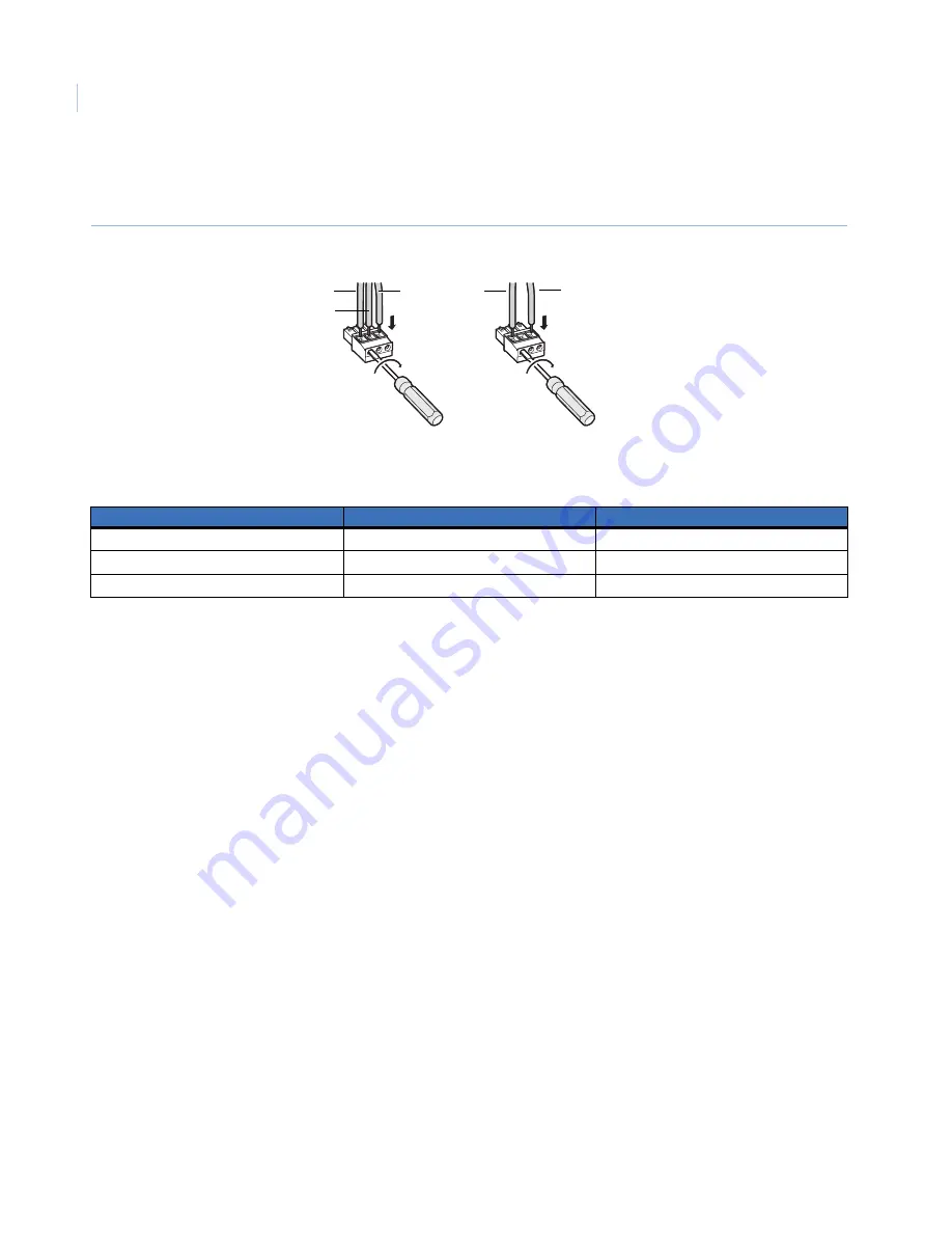
c. Tighten the screws to secure the inserted power wires. Make sure that the exposed wires are 

completely hidden after tightening the screws (

Figure 19

).

Figure 19. Power cord plug

Table 1

 shows the power plug terminals and the related wires.

d. Insert the power plug into the power terminals on the mounting side of the camera. Make sure the 

power plug is inserted into the power terminals firmly.

Power over Ethernet (PoE).  

When using PoE, connect a LAN cable (CAT5 or better) between a PoE 

device (such as a PoE hub) and the network connector of the camera.

Use all four pairs (eight pins) of the LAN cable.

The maximum cable length is 328 ft. (100 m).

Make sure the PoE device you use is compliant with IEEE802.3af standard.

When connecting both the 12 VDC/24 VAC power supply and the PoE device for power supply, 
the PoE will be used for power supply. 

If the LAN cable is disconnected, wait at least 2 seconds before re-inserting the cable to ensure the 
PoE device supplies power.

3. Connect a LAN cable (CAT5 or better) to the network connector on the mounting side of the camera 

(

Figure 20

).

Table 1.

Power plug terminals

Power plug

24 VAC in

12 VDC in

A

2 N

-

B

GND

NC

C

1 L

+

A    B 

   C

A    B    

C

12 VDC

24 VAC

C

B

-

+

A

Summary of Contents for CamPlus 2 GEC-IP2D

Page 1: ...INSERT ADJU ST LO CK DO CO ME VER DOME CO VER g GE Security 1065600A CamPlus 2 Plastic Dome IP Camera Installation Manual ...

Page 2: ...s and patents GE and the GE monogram are registered trademarks of General Electric Company CamPlus 2 Plastic Dome IP Camera product and logo are registered trademarks of GE Security Other trade names used in this document may be trademarks or registered trademarks of the manufacturers or vendors of the respective products Intended use Use this product only for the purpose it was designed for refer...

Page 3: ...work security 9 Mount bracket installation 10 Camera installation 12 Connections 15 Adjustments 20 Shooting direction adjustment 20 Angular field of view and focus adjustment 22 SD memory cards 23 Insert the SD memory card 23 Remove the SD card 24 Software installation 25 Configure the network settings 25 Operation guidelines 27 Troubleshooting 28 Contacting us 29 Online resources 29 ...

Page 4: ...CamPlus 2 Plastic Dome IP Camera Installation Manual iv ...

Page 5: ...or instructions on accessing our online publication library Note A qualified service person complying with all applicable codes should perform all required hardware installation The following conventions are used in this document Safety terms and symbols These terms may appear in this manual Related documentation The CD ROM contains the CamPlus 2 Plastic Dome IP Camera User Manual Refer to the Use...

Page 6: ...ng in high resolution MPEG 4 images can be monitored while recording JPEG images When you connect with a PoE power over Ethernet IEEE802 3af compliant device power is supplied when you connect the LAN cable Audio captured by the built in microphone can be monitored with your PC via a network The camera can be installed on a ceiling or a wall using the provided camera mount bracket When using an op...

Page 7: ... label will be requested when you contact technical service We recommend you paste one of the labels onto the CD ROM case System requirements The system requirements include the following OS Windows 2000 SP4 Windows XP Home Edition SP2 Windows XP Professional Edition SP2 Windows Vista Business 32 bit Computer IBM PC AT compatible CPU Pentium 4 2 4 GHz or faster Memory 512 MB or more Monitor 1024 x...

Page 8: ...rols inside the dome DOME CO VER INSERT ADJUST LOCK DO CO ME VER N DOME CO VER INSERT ADJUST LOCK DO CO ME VER N LEDs Indicators on off switch Monitor out connection Image tilt adjustment ring SD memory card slot Zoom ring Focus ring Dome cover lock marker Panning table Panning table fixing screw Tilting table Dome cover lock marker Microphone hole Inner dome Clear dome ...

Page 9: ...nsert an SD memory card See SD memory cards on page 23 Zoom ring Use this ring to adjust the angular field of view See Angular field of view and focus adjustment on page 22 Focus ring Use this ring to adjust the focus See Angular field of view and focus adjustment on page 22 Tilting table Rotate this table to adjust the tilting angle of the camera See Image tilt adjustment on page 21 Panning table...

Page 10: ...nnections on page 15 Initial set button Use this button to reset the camera to the default settings Turn off the power to the camera Then turn on the power to the camera while holding this button down and wait about five seconds without releasing the button Wait about 30 seconds after releasing the button The camera will restart and the settings including the network and the date time will be init...

Page 11: ...nal device and the safety wire and then bundle them using the cable tie provided See Camera installation on page 12 Attach the safety wire to the safety wire holder of the camera See Camera installation on page 12 Connect the power cord from a 12 VDC or 24 VAC power supply a LAN cable CAT5 or better and if using an optional external device connect it also See Connections on page 15 Mount the camer...

Page 12: ...subject Figure 5 Camera location for adjustment Avoid installing the camera in the following locations Locations where a chemical agent is used such as a swimming pool Locations subject to steam and oil smoke Locations near flammable gas or vapor Locations where radiation or x ray emissions are produced Locations where corrosive gas is produced Locations where it may be damaged by briny air such a...

Page 13: ...s connected to a network that includes PCs make sure the system is not infected by computer viruses or other malicious entities use a regularly updated antivirus program anti spyware program etc Protect your network against unauthorized access by restricting users to those who log in with an authorized user name and password Apply measures such as user authentication to protect your network agains...

Page 14: ...s of the camera mount bracket are also designed to allow you to mount the bracket on a two gang junction box 2 Secure the camera mount bracket Figure 8 Use a sufficient quantity of mounting bolts appropriate to the mounting surface Tighten the bolts securely to ensure that the installed mount bracket can support more than five times the weight of the camera Figure 8 Fasten the bracket If the mount...

Page 15: ...11 The camera may also be mounted without drilling a wiring hole by removing the wiring tab on the side of the camera Figure 9 Figure 9 Mount without hole Tab Remove tab Wiring hole ...

Page 16: ...he safety wire and then bundle them using the cable tie provided See Figure 4 on page 7 3 Attach the safety wire to the camera After attaching the safety wire to the camera pull the safety wire and confirm that the loop at the end of the safety wire is securely hooked on the safety wire holder Figure 11 Figure 11 Attach safety wire Note The safety wire is designed to support only the weight of the...

Page 17: ...is level and mounted firmly The main body cannot be rotated 7 Turn on the camera power 8 Adjust the angular field of view and focus See Angular field of view and focus adjustment on page 22 9 Attach the dome cover to the main body Insert the dome cover into the camera body so that the Dome Cover indication is aligned with the Insert position indication mark Figure 13 Figure 13 Insert position alig...

Page 18: ...k position indication mark Figure 15 Figure 15 Lock position alignment and dome cover screw hole 12 Secure the dome cover to the main body using the provided dome cover fixing screw Figure 15 Note The hole located near the dome cover lock marker is the microphone hole Do not screw onto the microphone hole CAUTION When adjusting images if the Dome Cover and the Adjust indication marks are not prope...

Page 19: ...tions to connect a power supply to the camera Figure 17 Figure 17 Power cord terminals 12 VDC 24 VAC power supply When using a 12 VDC 24 VAC power supply do the following a Remove 0 12 to 0 28 in 3 to 7 mm of the outer jacket of the power wire AWG 16 to 28 single core twisted from a 12 VDC or 24 VAC power supply and twist the core of the power wire to prevent a short circuit Figure 18 Figure 18 Re...

Page 20: ...tter between a PoE device such as a PoE hub and the network connector of the camera Use all four pairs eight pins of the LAN cable The maximum cable length is 328 ft 100 m Make sure the PoE device you use is compliant with IEEE802 3af standard When connecting both the 12 VDC 24 VAC power supply and the PoE device for power supply the PoE will be used for power supply If the LAN cable is disconnect...

Page 21: ... and insert the cables from the external device into the external I O terminals plug until the exposed core wires are completely hidden Figure 22 Figure 22 External I O terminal plug c Tighten the screws to secure the inserted cables Make sure that the exposed core wires are completely hidden after tightening the screws Note Do not connect two more wires directly to a terminal If it is necessary t...

Page 22: ...rminals Alarm in No voltage make contact input 4 to 5 VDC pulled up Off Open or 4 to 5 VDC On Make contact with GND required drive current 1 mA or more Alarm out and AUX out Open collector output external max applied voltage 20 VDC Open 4 to 5 VDC internally pulled up Close Output voltage of 1 VDC or less 100 mA or less External I O terminals GND AUX output AUX OUT Alarm input ALARM IN Alarm outpu...

Page 23: ... straight and use a switching hub or router that is compliant with 10Base T 100Base TX Figure 26 Connect using PoE A power supply is required for each network camera When you use a PoE device a 24 VAC 12 VDC power supply is not necessary Camera PC To 12 VDC or 24 VAC power LAN cable CAT5 cross Video monitor for setup adjustments PoE device hub Camera Camera LAN cable CAT5 straight LAN cable CAT5 s...

Page 24: ...tion adjustment panning Loosen the panning table fixing screw and rotate the panning table to determine the horizontal position available range 320 In the home position the three marks are in a straight line Figure 27 To adjust the position rotate the panning table clockwise 180 and counterclockwise 140 After determining the position secure the panning table with the panning table fixing screw Fig...

Page 25: ...the upside down images The viewing angle Figure 28 will be Horizontal 21 TELE to 73 WIDE Vertical 16 TELE to 54 WIDE Figure 28 Vertical position Image tilt adjustment Adjust the image tilt by rotating the image tilt adjustment ring available range 100 See Figure 29 Note The closer the horizontal position to a level the more the dome cover shade may appear in images Figure 29 Image tilt adjustment ...

Page 26: ...g 1 Loosen the zoom lock screw and then rotate the zoom ring to adjust angular field of view according to the subject When the angular field of view is determined tighten the zoom lock screw 2 Loosen the focus lock screw and then rotate the focus ring to adjust focus When the subject is focused tighten the focus lock screw Figure 30 Angular field of view and focus Note When changing the angular fi...

Page 27: ...amera to someone for repair Replace the SD memory card when you have periodic maintenance done on the camera Insert the SD memory card To insert the SD memory card do the following 1 Turn the camera off 2 Remove the dome cover fixing screw Figure 31 and then detach the dome cover from the main body See Camera installation on page 12 Figure 31 Dome cover fixing screw 3 Insert an SD memory card into...

Page 28: ...up menu Basic setup tab select Not use for About SD memory card Refer to the User Manual 3 Remove the dome cover fixing screw and then detach the dome cover from the main body See Camera installation on page 12 4 Remove the SD memory card after releasing the lock by pushing the SD memory card once 5 Attach the dome cover See Camera installation on page 12 ...

Page 29: ...If the Easy IP Setup software does not work to configure the camera s network settings go to the Network setup page from the Setup menu in the CamPlus 2 IP Viewer software to configure the camera s network settings and the PC individually Refer to the User Manual If you are using Windows XP 5P2 the Windows security alert window may display when you start the Easy IP Setup software If this happens ...

Page 30: ...ply See Figure 33 on page 26 When you use a DHCP server it is possible to set DNS to AUTO Figure 33 IP settings It may take about 30 seconds to complete the settings upload to the camera The settings may be invalidated when the 24 VAC or 12 VDC power supply is cut or when the LAN cable is disconnected before completing the upload If this happens configure the settings again When using a firewall i...

Page 31: ...l be inoperable for approximately 30 seconds after you turn the camera on Unplug the camera during electrical storms or when the camera goes unused for long periods of time Use only with an approved cart stand tripod bracket or table If you use a cart use caution Move the cart so you do not tip it over Do not tamper with the polarized or grounding type plug A polarized plug has two blades with one...

Page 32: ...er on For a 24 VAC 12 VDC power supply make sure the power supply is connected to the power cord terminal Verify that the cable is firmly connected For a PoE device power supply make sure the PoE device and the network connector on the mounting side of the camera are connected using a LAN cable 4 pair Verify that the cable is firmly connected See Connections on page 15 Depending on the PoE device ...

Page 33: ...Policy Statement Customer service and technical support From the Customer Support menu select Customer Service or Technical Application Select the appropriate product category for the contact information or use the menu to select a location outside the US Table 2 Technical support North America Latin America T 888 GE Security 888 437 3287 Toll free in the US Puerto Rico and Canada 503 885 5700 out...

Page 34: ...CamPlus 2 Plastic Dome IP Camera Installation Manual 30 ...

Reviews: