APPENDIX B
B-2
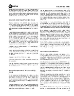
ACTION
REFERENCE
MALFUNCTION
8.
Phase overcurrent
protection not energiz-
ing trip relay(s).
9.
Phase overcurrent
protection causes trip
but no alarm.
10. Phase instantaneous
trips not operating.
2. Check that the correct voltage transformer sens-
ing system, secondary voltage and VT feeder
primary voltage have been entered in setpoints.
Verify that all the voltage sensing wiring is correct.
3. Ensure that the trip relay wiring to the breaker trip
circuit is correct at terminals 41 and 57.
4. Verify which relay(s) has been selected to be
activated by the under or overvoltage condition, in
the voltage setpoints.
5. Check the under or overvoltage trip level setpoint
and verify that the voltage is exceeding this level.
Determine the under or overvoltage trip delay
from the setpoints, and verify that the fault condi-
tion is present for longer than this time.
6. Perform calibration mode relay test to verify the
operation of the trip relay.
1. Check phase CT rating, connections and polarity.
2. Verify that the correct protection curve, pickup
level and curve number have been entered in
setpoints.
3. If the custom curve has been chosen, use the Line
Down key to check the time to trip for each breakpoint.
4. Perform calibration mode relay test to verify the
operation of the trip relay.
1. Check that the phase overcurrent alarm is ena-
bled in setpoints.
2. Verify the relay to which the alarm signal has
been assigned.
3. Check that the alarm level setpoint is less than
the trip level setpoint and that the fault current is
between these two values.
4. Check the phase overcurrent alarm time delay
setpoint and ensure that the alarm condition is
present for longer than this time. Note that if the
overcurrent level rises to the trip level before the
timed period, a trip will occur before the alarm.
5. Perform calibration mode relay test to verify op-
eration of the assigned relay(s).
1. Check that the phase instantaneous trips are
enabled in setpoints.
2. Check the phase instantaneous trip level setpoint
and verify that the current is exceeding this level.
Setpoints page 9 and relay
wiring diagram.
Relay wiring diagram.
Setpoints page 9.
Setpoints page 9.
Setpoints page 8.
Setpoints page 2 and instruc-
tion manual section 6.
Setpoints page 2.
Setpoints page 8.
Setpoints page 2.
Setpoints page 2.
Setpoints page 2.
Setpoints page 2.
Setpoints page 8.
Setpoints page 2.
Setpoints page 2.
Summary of Contents for 565
Page 6: ...INSTALLATION 2 2 Figure 2 1 Mounting Details ...
Page 7: ...INSTALLATION 2 3 Figure 2 2 Mounting Arrangement with Relay Collar ...
Page 12: ...INSTALLATION 2 8 Figure 2 5 565 Relay Typical Wiring ...
Page 13: ...INSTALLATION 2 9 Figure 2 6 Voltage Sensing Wire ...
Page 14: ...INSTALLATION 2 10 Figure 2 7A 565 with MTM CT and Open Delta VT Typical Wiring ...
Page 15: ...INSTALLATION 2 11 Figure 2 7B 565 with MTM CT and Wye VT Typical Wiring ...
Page 16: ...INSTALLATION 2 12 Figure 2 8A Open Delta VT and CT MTM Typical Wiring ...
Page 17: ...INSTALLATION 2 13 Figure 2 8B Wye VT and CT MTM Typical Wiring ...
Page 18: ...INSTALLATION 2 14 Figure 2 9 MTM Mounting Dimensions ...
Page 19: ...INSTALLATION 2 15 Figure 2 10 565 Rear Panel Layout ...
Page 20: ......
Page 23: ...DISPLAY AND KEYBOARD 3 3 Figure 4 1 565 Relay Front Panel ...
Page 28: ......
Page 132: ......
Page 142: ...CURVE INFORMATION ANDTABLES 7 10 Figure 7 9 IEC A Curves ...
Page 143: ...CURVE INFORMATION ANDTABLES 7 11 Figure 7 10 IEC B Curves ...
Page 144: ...CURVE INFORMATION ANDTABLES 7 12 Figure 7 11 IEC C Curves ...
Page 176: ...RELAYTESTING 8 2 Figure 8 1 Secondary Injection Test Setup ...
Page 180: ......
Page 184: ......
Page 192: ...APPENDIX C C 2 Figure C1 System Controller Block Diagram 1 2 ...
Page 193: ...APPENDIX C C 3 Figure C2 System Controller Block Diagram 2 2 ...
Page 194: ......
Page 198: ......


