


3-36
B90 Low Impedance Bus Differential System
GE Multilin
3.3 DIRECT INPUT/OUTPUT COMMUNICATIONS
3 HARDWARE
3
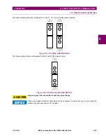
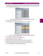
Figure 3–40: IEEE C37.94 TIMING SELECTION SWITCH SETTING
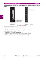
Modules shipped since January 2012 have status LEDs that indicate the status of the DIP switches, as shown in the follow-
ing figure.
Figure 3–41: STATUS LEDS
The clock configuration LED status is as follows:
•
Flashing green — loop timing mode while receiving a valid data packet
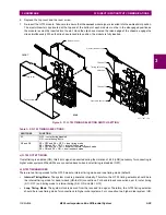
Cover screw
Top cover
Bottom cover
Ejector/inserter clip
Ejector/inserter clip
Timing selection
switches
Channel 1
Channel 2
FRONT
REAR
831774A3.CDR
Tx1
Tx2
Rx1
Rx2
Tx1
Tx2
CH1 Link/Activity LED
CH2 Link/Activity LED
COMMS
2B
C37.94SM
1300nm single-mode
ELED
2 channel
Technical support:
Tel: (905)294-6222
Fax: (905)201-2098
(NORTH AMERICA)
1 800 547-8629
Made in Canada
GE Multilin
REV. D
CH1 Clock Configuration LED
CH2 Clock Configuration LED
FRONT VIEW
REAR VIEW
842837A1.cdr
Summary of Contents for B90
Page 10: ...x B90 Low Impedance Bus Differential System GE Multilin TABLE OF CONTENTS ...
Page 284: ...5 166 B90 Low Impedance Bus Differential System GE Multilin 5 8 TESTING 5 SETTINGS 5 ...
Page 334: ...10 8 B90 Low Impedance Bus Differential System GE Multilin 10 2 BATTERIES 10 MAINTENANCE 10 ...
Page 338: ...A 4 B90 Low Impedance Bus Differential System GE Multilin A 1 PARAMETER LISTS APPENDIX A A ...
Page 460: ...C 30 B90 Low Impedance Bus Differential System GE Multilin C 7 LOGICAL NODES APPENDIX C C ...
Page 476: ...E 10 B90 Low Impedance Bus Differential System GE Multilin E 1 IEC 60870 5 104 APPENDIX E E ...
Page 502: ...viii B90 Low Impedance Bus Differential System GE Multilin INDEX ...