


5-160
B90 Low Impedance Bus Differential System
GE Multilin
5.7 INPUTS/OUTPUTS
5 SETTINGS
5
DIRECT INPUT 9 DEVICE ID
: "4"
DIRECT INPUT 9 BIT NUMBER
: "3"
DIRECT INPUT 9 DEFAULT STATE
: select "On" for security, select "Off" for dependability
Now the three blocking signals are available in UR IED 1 as
DIRECT INPUT 7 ON
,
DIRECT INPUT 8 ON
, and
DIRECT INPUT 9
ON
. Upon losing communications or a device, the scheme is inclined to block (if any default state is set to “On”), or to trip
the bus on any overcurrent condition (all default states set to “Off”).
EXAMPLE 2: PILOT-AIDED SCHEMES
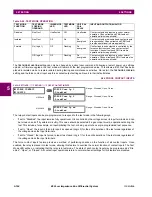
Consider a three-terminal line protection application shown in the figure below.
Figure 5–70: THREE-TERMINAL LINE APPLICATION
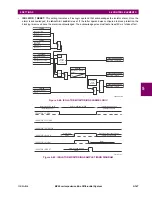
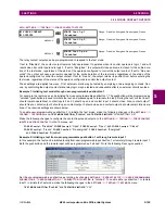
Assume the Hybrid Permissive Overreaching Transfer Trip (Hybrid POTT) scheme is applied using the architecture shown
below. The scheme output operand
HYB POTT TX1
is used to key the permission.
Figure 5–71: SINGLE-CHANNEL OPEN-LOOP CONFIGURATION
In the above architecture, Devices 1 and 3 do not communicate directly. Therefore, Device 2 must act as a ‘bridge’. The fol-
lowing settings should be applied:
UR IED 1:
DIRECT OUT 2 OPERAND:
"
HYB POTT TX1
"
DIRECT INPUT 5 DEVICE ID:
"2"
DIRECT INPUT 5 BIT NUMBER:
"2" (this is a message from IED 2)
DIRECT INPUT 6 DEVICE ID:
"2"
DIRECT INPUT 6 BIT NUMBER:
"4" (effectively, this is a message from IED 3)
UR IED 3:
DIRECT OUT 2 OPERAND:
"
HYB POTT TX1
"
DIRECT INPUT 5 DEVICE ID:
"2"
DIRECT INPUT 5 BIT NUMBER:
"2" (this is a message from IED 2)
DIRECT INPUT 6 DEVICE ID:
"2"
DIRECT INPUT 6 BIT NUMBER:
"3" (effectively, this is a message from IED 1)
UR IED 2:
DIRECT INPUT 5 DEVICE ID:
"1"
DIRECT INPUT 5 BIT NUMBER:
"2"
DIRECT INPUT 6 DEVICE ID:
"3"
DIRECT INPUT 6 BIT NUMBER:
"2"
842713A1.CDR
UR IED 1
UR IED 2
UR IED 3
842714A1.CDR
UR IED 1
TX1
RX1
UR IED 2
RX2
TX2
RX1
TX1
UR IED 3
RX1
TX1
Summary of Contents for B90
Page 10: ...x B90 Low Impedance Bus Differential System GE Multilin TABLE OF CONTENTS ...
Page 284: ...5 166 B90 Low Impedance Bus Differential System GE Multilin 5 8 TESTING 5 SETTINGS 5 ...
Page 334: ...10 8 B90 Low Impedance Bus Differential System GE Multilin 10 2 BATTERIES 10 MAINTENANCE 10 ...
Page 338: ...A 4 B90 Low Impedance Bus Differential System GE Multilin A 1 PARAMETER LISTS APPENDIX A A ...
Page 460: ...C 30 B90 Low Impedance Bus Differential System GE Multilin C 7 LOGICAL NODES APPENDIX C C ...
Page 476: ...E 10 B90 Low Impedance Bus Differential System GE Multilin E 1 IEC 60870 5 104 APPENDIX E E ...
Page 502: ...viii B90 Low Impedance Bus Differential System GE Multilin INDEX ...