


GE Multilin
B90 Low Impedance Bus Differential System
5-141
5 SETTINGS
5.6 CONTROL ELEMENTS
5
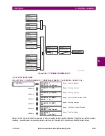
5.6.4 DIGITAL ELEMENTS
PATH: SETTINGS
CONTROL ELEMENTS
DIGITAL ELEMENTS
DIGITAL ELEMENT 1(48)
There are 48 identical digital elements available, numbered 1 to 48. A digital element can monitor any FlexLogic operand
and present a target message and/or enable events recording depending on the output operand state. The digital element
settings include a name which will be referenced in any target message, a blocking input from any selected FlexLogic oper-
and, and a timer for pickup and reset delays for the output operand.
•
DIGITAL ELEMENT 1 INPUT:
Selects a FlexLogic operand to be monitored by the digital element.
•
DIGITAL ELEMENT 1 PICKUP DELAY:
Sets the required time delay from element pickup to element operation. If a
pickup delay is not required, set to "0". To avoid nuisance alarms, set the delay greater than the operating time of the
breaker.
•
DIGITAL ELEMENT 1 RESET DELAY:
Sets the time delay to reset. If a reset delay is not required, set to “0”.
•
DIGITAL ELEMENT 1 PICKUP LED
: This setting enables or disabled the digital element pickup LED. When set to
“Disabled”, the operation of the pickup LED is blocked.
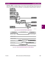
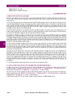
Figure 5–59: DIGITAL ELEMENT SCHEME LOGIC
DIGITAL ELEMENT 1
DIGITAL ELEMENT 1
FUNCTION: Disabled
Range: Disabled, Enabled
MESSAGE
DIG ELEM 1 NAME:
Dig Element 1
Range: 16 alphanumeric characters
MESSAGE
DIG ELEM 1 INPUT:
Off
Range: FlexLogic operand
MESSAGE
DIG ELEM 1 PICKUP
DELAY: 0.000
s
Range: 0.000 to 999999.999 s in steps of 0.001
MESSAGE
DIG ELEM 1 RESET
DELAY: 0.000
s
Range: 0.000 to 999999.999 s in steps of 0.001
MESSAGE
DIG ELEMENT 1
PICKUP LED: Enabled
Range: Disabled, Enabled
MESSAGE
DIG ELEM 1 BLOCK:
Off
Range: FlexLogic operand
MESSAGE
DIGITAL ELEMENT 1
TARGET: Self-reset
Range: Self-reset, Latched, Disabled
MESSAGE
DIGITAL ELEMENT 1
EVENTS: Disabled
Range: Disabled, Enabled
SETTING
DIGITAL ELEMENT 01
FUNCTION:
Enabled = 1
DIGITAL ELEMENT 01
BLOCK:
Off = 0
FLEXLOGIC OPERANDS
DIG ELEM 01 DPO
DIG ELEM 01 PKP
SETTING
827042A2.VSD
DIGITAL ELEMENT 01
INPUT:
Off = 0
SETTING
INPUT = 1
RUN
t
PKP
t
RST
DIGITAL ELEMENT 01
PICKUP DELAY:
SETTINGS
DIGITAL ELEMENT 01
RESET DELAY:
AND
SETTING
DIGITAL ELEMENT 01
NAME:
DIG ELEM 01 OP
Summary of Contents for B90
Page 10: ...x B90 Low Impedance Bus Differential System GE Multilin TABLE OF CONTENTS ...
Page 284: ...5 166 B90 Low Impedance Bus Differential System GE Multilin 5 8 TESTING 5 SETTINGS 5 ...
Page 334: ...10 8 B90 Low Impedance Bus Differential System GE Multilin 10 2 BATTERIES 10 MAINTENANCE 10 ...
Page 338: ...A 4 B90 Low Impedance Bus Differential System GE Multilin A 1 PARAMETER LISTS APPENDIX A A ...
Page 460: ...C 30 B90 Low Impedance Bus Differential System GE Multilin C 7 LOGICAL NODES APPENDIX C C ...
Page 476: ...E 10 B90 Low Impedance Bus Differential System GE Multilin E 1 IEC 60870 5 104 APPENDIX E E ...
Page 502: ...viii B90 Low Impedance Bus Differential System GE Multilin INDEX ...