


3-26
B90 Low Impedance Bus Differential System
GE Multilin
3.3 DIRECT INPUT/OUTPUT COMMUNICATIONS
3 HARDWARE
3
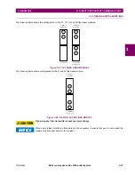
Figure 3–25: DIRECT INPUT AND OUTPUT SINGLE/DUAL CHANNEL COMBINATION CONNECTION
The inter-relay communications modules are available with several interfaces and some are outlined here in more detail.
Those that apply depend on options purchased. The options are outlined in the Inter-Relay Communications section of the
Order Code tables in Chapter 2. All of the fiber modules use ST type connectors.
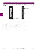
3.3.2 FIBER: LED AND ELED TRANSMITTERS
The following figure shows the configuration for the 7A, 7B, 7C, 7H, 7I, and 7J fiber-only modules.
Figure 3–26: LED AND ELED FIBER MODULES
842013A2.CDR
Channel 1
Channel 2
Tx1
UR 2
Tx2
Rx1
Rx2
Tx
UR 1
Rx
Tx
UR 3
Rx
7A, 7B, and
7C modules
7H, 7I, and
7J modules
1 channel
2 channels
Rx1
Rx1
Rx2
Tx1
Tx1
Tx2
831719A3.CDR
Summary of Contents for B90
Page 10: ...x B90 Low Impedance Bus Differential System GE Multilin TABLE OF CONTENTS ...
Page 284: ...5 166 B90 Low Impedance Bus Differential System GE Multilin 5 8 TESTING 5 SETTINGS 5 ...
Page 334: ...10 8 B90 Low Impedance Bus Differential System GE Multilin 10 2 BATTERIES 10 MAINTENANCE 10 ...
Page 338: ...A 4 B90 Low Impedance Bus Differential System GE Multilin A 1 PARAMETER LISTS APPENDIX A A ...
Page 460: ...C 30 B90 Low Impedance Bus Differential System GE Multilin C 7 LOGICAL NODES APPENDIX C C ...
Page 476: ...E 10 B90 Low Impedance Bus Differential System GE Multilin E 1 IEC 60870 5 104 APPENDIX E E ...
Page 502: ...viii B90 Low Impedance Bus Differential System GE Multilin INDEX ...