


1-8
B90 Low Impedance Bus Differential System
GE Multilin
1.3 ENERVISTA UR SETUP SOFTWARE
1 GETTING STARTED
1
c) CONFIGURING ETHERNET COMMUNICATIONS
Before starting, verify that the Ethernet network cable is properly connected to the Ethernet port on the back of the relay. To
setup the relay for Ethernet communications, you define a Site, then add the relay as a Device at that site.The computer
and UR device must be on the same subnet.
12. Select the “UR” device from the EnerVista Launchpad to start EnerVista UR Setup.
13. Click the
Device Setup
button to open the Device Setup window, then click the
Add Site
button to define a new site.
14. Enter the desired site name in the “Site Name” field. If desired, a short description of site can also be entered along
with the display order of devices defined for the site. In this example, we use “Location 2” as the site name. Click the
OK
button when complete.
15. The new site appears in the upper-left list in the EnerVista UR Setup window. Click the
Device Setup
button then
select the new site to re-open the Device Setup window.
16. Click the
Add Device
button to define the new device.
17. Enter the desired name in the “Device Name” field and a description (optional) of the site.
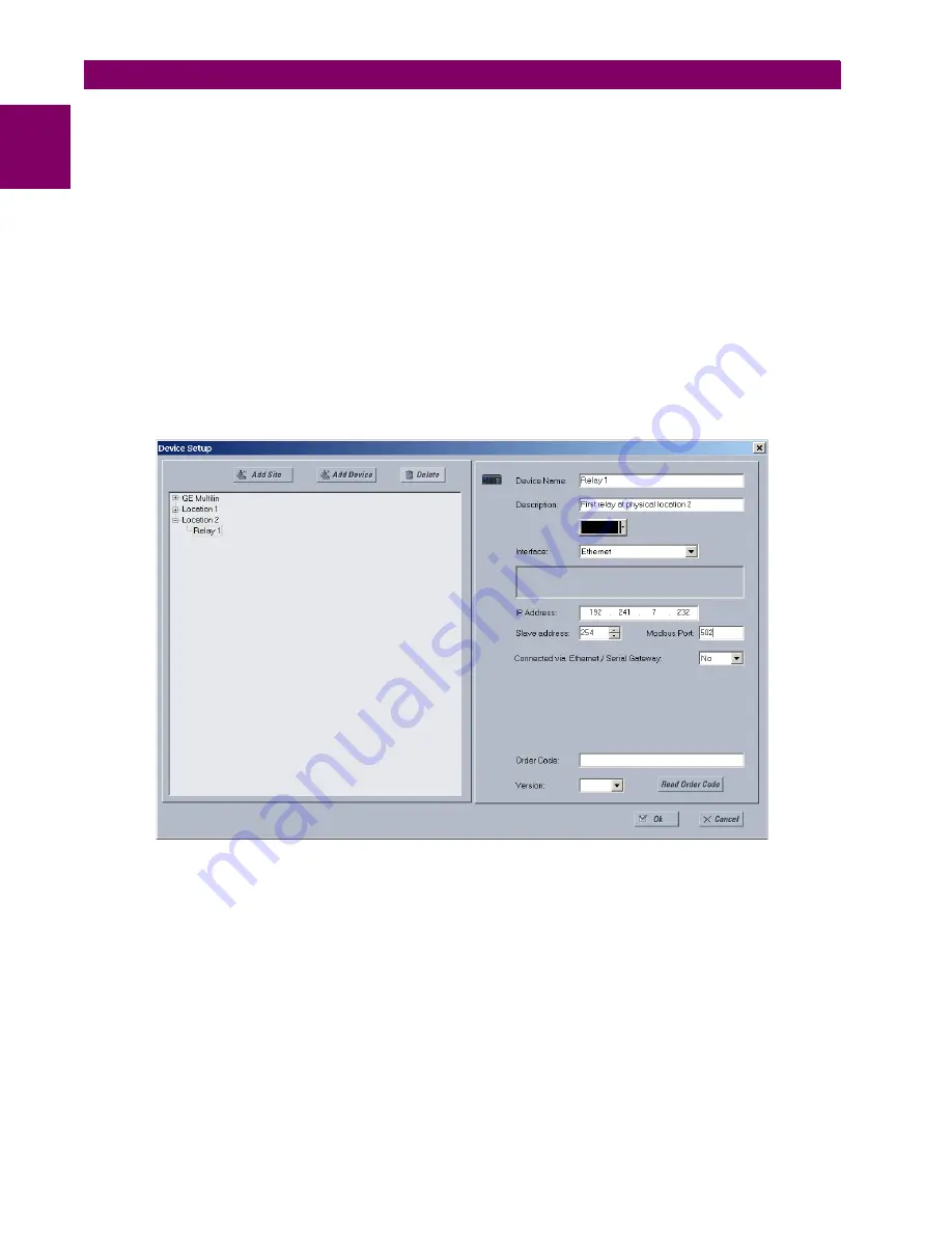
18. Select “Ethernet” from the
Interface
drop-down list. This displays a number of interface parameters that must be
entered for proper Ethernet functionality.
Figure 1–7: CONFIGURING ETHERNET COMMUNICATIONS
19. Enter the relay IP address specified in the front panel
SETTINGS
PRODUCT SETUP
COMMUNICATIONS
NETWORK
IP ADDRESS
in the “IP Address” field.
20. Enter the relay slave address and Modbus port address values from the respective settings in the front panel
SETTINGS
PRODUCT SETUP
COMMUNICATIONS
MODBUS PROTOCOL
menu.
21. Click the
Read Order Code
button to connect to the B90 device and upload the order code. If an communications
error occurs, ensure that the three EnerVista UR Setup values entered in the previous steps correspond to the relay
setting values.
22. Click
OK
when the relay order code has been received. The new device is added to the Site List window (or Online
window) located in the top left corner of the main EnerVista UR Setup window.
The Site Device has now been configured for Ethernet communications. Proceed to the
Connecting to the B90
section to
begin communications.
Summary of Contents for B90
Page 10: ...x B90 Low Impedance Bus Differential System GE Multilin TABLE OF CONTENTS ...
Page 284: ...5 166 B90 Low Impedance Bus Differential System GE Multilin 5 8 TESTING 5 SETTINGS 5 ...
Page 334: ...10 8 B90 Low Impedance Bus Differential System GE Multilin 10 2 BATTERIES 10 MAINTENANCE 10 ...
Page 338: ...A 4 B90 Low Impedance Bus Differential System GE Multilin A 1 PARAMETER LISTS APPENDIX A A ...
Page 460: ...C 30 B90 Low Impedance Bus Differential System GE Multilin C 7 LOGICAL NODES APPENDIX C C ...
Page 476: ...E 10 B90 Low Impedance Bus Differential System GE Multilin E 1 IEC 60870 5 104 APPENDIX E E ...
Page 502: ...viii B90 Low Impedance Bus Differential System GE Multilin INDEX ...