


4-14
B90 Low Impedance Bus Differential System
GE Multilin
4.3 FACEPLATE INTERFACE
4 HUMAN INTERFACES
4
4.3.2 LED INDICATORS
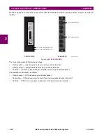
a) ENHANCED FACEPLATE
The enhanced front panel display provides five columns of LED indicators. The first column contains 14 status and event
cause LEDs, and the next four columns contain the 48 user-programmable LEDs.
The RESET key is used to reset any latched LED indicator or target message, once the condition has been cleared (these
latched conditions can also be reset via the
SETTINGS
INPUT/OUTPUTS
RESETTING
menu). The RS232 port is
intended for connection to a portable PC.
The USER keys are not used in this unit.
Figure 4–17: TYPICAL LED INDICATOR PANEL FOR ENHANCED FACEPLATE
The status indicators in the first column are described below.
•
IN SERVICE
:
This LED indicates that control power is applied, all monitored inputs, outputs, and internal systems are
OK, and that the device has been programmed.
•
TROUBLE
: This LED indicates that the relay has detected an internal problem.
•
TEST MODE
:
This LED indicates that the relay is in test mode. For more information, see the Test Mode section in the
Settings chapter.
•
TRIP
:
This LED indicates that the FlexLogic operand serving as a trip switch has operated. This indicator always
latches; as such, a reset command must be initiated to allow the latch to be reset.
•
ALARM
:
This LED indicates that the FlexLogic operand serving as an alarm switch has operated. This indicator is
never latched.
•
PICKUP
:
This LED indicates that an element is picked up. This indicator is never latched.
The event cause indicators in the first column are described below.
Events cause LEDs are turned on or off by protection elements that have their respective target setting selected as either
“Enabled” or “Latched”. If a protection element target setting is “Enabled”, then the corresponding event cause LEDs
remain on as long as operate operand associated with the element remains asserted. If a protection element target setting
is “Latched”, then the corresponding event cause LEDs turn on when the operate operand associated with the element is
asserted and remain on until the RESET button on the front panel is pressed after the operand is reset.
All elements that are able to discriminate faulted phases can independently turn off or on the phase A, B, or C LEDs. This
includes phase instantaneous overcurrent, phase undervoltage, etc. This means that the phase A, B, and C operate oper-
ands for individual protection elements are ORed to turn on or off the phase A, B, or C LEDs.
•
VOLTAGE
: This LED indicates voltage was involved.
•
CURRENT
: This LED indicates current was involved.
•
FREQUENCY
: This LED indicates frequency was involved.
•
OTHER
: This LED indicates a composite function was involved.
•
PHASE A
: Not used.
•
PHASE B
: Not used.
842811A1.CDR
Summary of Contents for B90
Page 10: ...x B90 Low Impedance Bus Differential System GE Multilin TABLE OF CONTENTS ...
Page 284: ...5 166 B90 Low Impedance Bus Differential System GE Multilin 5 8 TESTING 5 SETTINGS 5 ...
Page 334: ...10 8 B90 Low Impedance Bus Differential System GE Multilin 10 2 BATTERIES 10 MAINTENANCE 10 ...
Page 338: ...A 4 B90 Low Impedance Bus Differential System GE Multilin A 1 PARAMETER LISTS APPENDIX A A ...
Page 460: ...C 30 B90 Low Impedance Bus Differential System GE Multilin C 7 LOGICAL NODES APPENDIX C C ...
Page 476: ...E 10 B90 Low Impedance Bus Differential System GE Multilin E 1 IEC 60870 5 104 APPENDIX E E ...
Page 502: ...viii B90 Low Impedance Bus Differential System GE Multilin INDEX ...