background image

DU-LC-0002-60 Rev C 6/14/06 GCX Corp. Page 11 of 11 

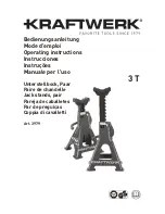
Tilt Tension Screws (2) 

Tilt Lever 

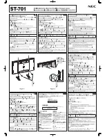
8.0  Cable Management   
 

One (1) Cable Clip (below left) is provided for managing 
cables along Roll Stand Post. Place loose cables inside Clip 
and slide Clip onto Post (below right). 


9.0  Adjusting Tilt and Tilt Tension 


Adjust tilt 

by loosening the Tilt Adjustment Lever (see 

Note

 below). Grasp 

the device and tilt to desired angle. Tighten Tilt Adjustment Lever to lock 
position. 
 

Adjust tilt tension

 by equally tightening or loosening two (2) Tilt Tension 

Screws with the 9/64'' hex wrench provided. Once overall tilt tension is set, 
use Tilt Adjustment Lever to fine tune/lock tilt position. 


10.0  Periodic Maintenance & Cleaning 

 
All fasteners associated with the mounting system should be inspected periodically and tightened as necessary. 
 

Cleaning the Mounting Assembly 

CAUTION:

  GCX makes no claims regarding the efficacy of the listed chemicals or processes as a means for controlling 

infection. Consult your hospital’s infection control officer or epidemiologist. To clean or sterilize mounted devices or 
accessory equipment, refer to the specific instructions delivered with those products. 

1.  The mounting assembly may be cleaned with most mild, non-abrasive solutions commonly used in the hospital 

environment (e.g. diluted bleach, ammonia, or alcohol solutions). 


2.  The surface finish will be permanently damaged by strong chemicals and solvents such as acetone or 

trichloroethylene. 


3.  Steel wool or other abrasive material should never be used. 


4.  Damage caused by the use of unapproved substances or processes will not be warranted. It is recommended that you 

test any cleaning solution on a small area of the mounting assembly that is not visible to verify compatibility. 


5.  Never submerge or allow liquids to enter the mounting assembly. Wipe any cleaning agents off the mounting assembly 

immediately, using a water-dampened cloth. Dry all parts thoroughly after cleaning.


Cable Clip

Roll Stand Cable Clip 

Cables 

Slide onto Post 

Note: 

The Tilt Adjustment Lever is a multi-

position clamping lever that operates by 
lifting, rotating, and releasing the handle. 
 

Summary of Contents for LiDCO

Page 1: ...e Roll Stand with Counterweight and Utility Basket 2 2 0 Attaching the Roll Stand Handle 3 3 0 Attaching the Power Outlet Strip 4 4 0 Attaching the Syringe Bag Holder 5 5 0 Attaching the Sensor Interf...

Page 2: ...s time 2 Slide Basket Clips over bottom end of Roll Stand Post and insert Post in center of Roll Stand Base below left Lay assembly on its side 3 Using a 1 2 13mm wrench fasten Post to Base using one...

Page 3: ...d Handle Parts Reference The following parts and hardware are provided for this procedure Tools Required Phillips screwdriver not provided 1 Fasten Handle to Post with two 2 10 32 x 9 16 PHMS as shown...

Page 4: ...rovided 1 Fasten Front Clamping Block to threaded mounting holes on rear of Power Outlet Strip with two 2 8 32 x 3 4 PHMS as shown below left 2 Position Power Outlet Strip on Roll Stand Post and faste...

Page 5: ...g parts and hardware are provided for this procedure Tools Required Phillips screwdriver not provided 1 Fasten Syringe Bag Holder around Post with two 2 10 32 x 9 16 PHMS as shown below Item Descripti...

Page 6: ...ook at desired height on Roll Stand Post and fasten Rear Block to Front Block below left with two 2 10 32 x 9 16 PHMS 2 Mount Sensor Interface by inserting four 4 mounting studs into slots in mounting...

Page 7: ...d front of Roll Stand and fasten to top of Post with three 3 10 32 x 7 8 FHMS as shown below Installation Note The Tilt Lever is a multi position clamping lever that operates by lifting rotating and r...

Page 8: ...oll Stand Procedures for both types of platform are included in this section Parts Reference The following parts and hardware are provided for this procedure Tools Required Phillips screwdriver not pr...

Page 9: ...d exposed to allow screws to fit into slots in VESA Mounting Plate 4 Guide two 2 upper screws into slots in VESA Mounting Plate below right Do not fully tighten these screws until instructed in Step 5...

Page 10: ...ar of the POC 153 or POC 155 below left Leave 1 4 6 mm of thread exposed to allow screws to fit into slots in VESA Mounting Plate 2 Guide two 2 upper screws into slots in VESA Mounting Plate below rig...

Page 11: ...tion Consult your hospital s infection control officer or epidemiologist To clean or sterilize mounted devices or accessory equipment refer to the specific instructions delivered with those products 1...

Reviews: