34
9. Setting the 3-Axis Gyro System
Page P.12
1. Model selection
If the remote control transmitter used by you permits switching between helicopter and wing models, select the model type
“flight model” since the quadrocopter does not need any mixer function in the transmitter.
2. Selection of the direction functions
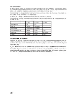
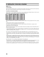
If one you use one of the transmitters from the table, you may now set the required direction function of the four control
channels (NOR = regular function direction; REV = reverse function direction).
GAUI
Futaba
JR
Hitech
AILE
NOR
NOR
REV
NOR
ELEV
NOR
NOR
REV
REV
THRO
REV
REV
NOR
NOR
RUDD
NOR
NOR
REV
NOR
If you use a transmitter from a manufacturer not listed, you need to determine the required direction functions in practical
tests.
3. Setting options at the 3-axis gyro system GU-344 GYRO
The 3-axis gyro system GU-344 GYRO can be set with a setting controller and DIP switches or by remote control.
a) Setting the GU-344 GYRO Manually
If the plug with the green connection cable is not connected to the receiver, the setting controller “A” and the DIP switch “1”
at the GU-344 GYRO are active.
• Turn the setting controller “A” from the left stop (minimum) to the right by 90° to get the basic setting of the gyro
sensitivity for the first test flights. Use a suitable mini screwdriver for this. The further the dial is turned to the right, the
higher the stabilising effect of the 3-axis gyro.
The 3-axis gyro system GU-344 GYRO also has 2 different flight settings that can be selected with the DIP switch “1”.
• If the DIP switch “1” is switched to the upper position “CRU” with the mini screwdriver, the control LED lights up red and
the quadrocopter behaves like a regular model helicopter. This setting is recommended for experienced model helicopter
pilots.
• If the DIP switch “1” is switched to the lower position “HOV” with the mini screwdriver, the control LED lights up green and
the quadrocopter is suitable for beginners learning hover flight. In this setting, the 3-axis gyro system receives the control
signals of the transmitter slightly and an exponential share is mixed in (see charts in the middle of page P.12). This permits
finer control of the quadrocopter in hover flight.
Use the DIP switch “2” to set two different flight alignments of the quadrocopter.
• If the DIP switch “2” is switched to the upper position, the X-flight alignment is activated. The centre between the motor
boom arms 1 and 4, where the flight direction indicator ball is installed, is at the front in flight direction.
• If the DIP switch “2” is switched to the lower position, the cross flight alignment is activated. If the 3-axis gyro system GU-
344 GYRO is also installed turned by 45°, the motor boom arm 1 is at the front in flight direction (also see page P.16).

