33
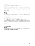
Page P.9
Upper figure:
Attach the propeller tappet on the motor shafts. The grub screws must interlock with the prepared groove of the motor
shaft.
When installing the propellers, observe that two propellers turn clockwise (label 8B) and two propellers turn
counter-clockwise (label 8A).
Lower figure:
After correct assembly, motors 1 and 3 with propellers 8A must turn counterclockwise and motors 2 and 4 with propellers
8B must turn clockwise.
Always observe correct rotating direction of the motors and correct assembly of the propellers during the first motor test
runs.
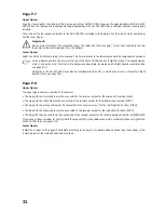
Page P.10
Upper figure:
Cut out the cover hood along the marked cutting line and glue the four washers on with liquid instant adhesive.
Lower figure:
If assembled correctly, the cover hood will be kept in the correct position automatically by the four magnets.
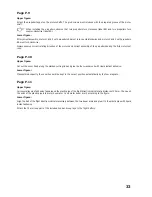
Page P.11
Upper figure:
Coil several layers of adhesive tape around the plastic pipe of the flight direction indicator at a distance of 50 mm. Then push
the ends of the plastic pipe into motor boom arm 1 and motor boom arm 4 according to the figure.
Lower figure:
Align the ball of the flight direction indicator precisely between the two boom arms and glue it to the plastic pipe with liquid
instant adhesive.
Attach the 75 mm loop part of the included hook-and-loop tape to the flight battery.

